26 - 2
26.1 System Configuration
26.1 System Configuration
Select a system configuration suitable for your application.
Conventions used in this section
Numbers (e.g. ) of System configuration and connection conditions correspond
to the numbers (e.g. ) of System equipment.
Use these numbers as references when confirming models and applications.
1 System configuration and connection conditions
*1 The PLC connection type and communication interface for printer connection are shown below.
Remark
System configuration between GOT and PLC
For the system configuration between the GOT and PLC, refer to the
corresponding section.
• MITSUBISHI PLC CONNECTIONS ( Sections 2 to 8)
• THIRD PARTY PLC CONNECTIONS ( Sections 9 to 18)
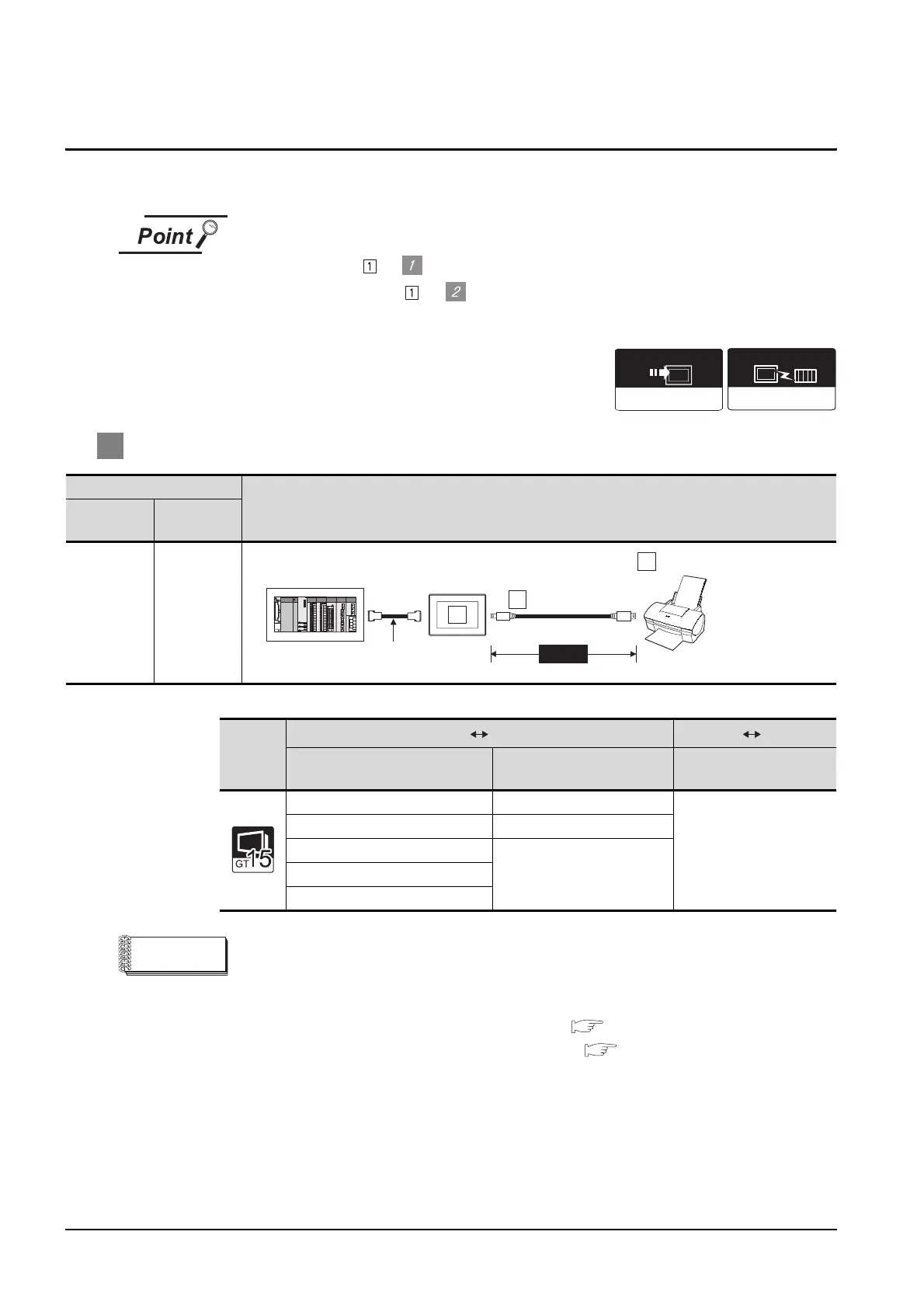
Connection conditions
System Configuration
Number of
GOT
Distance
1
Varies
according to
the printer's
specifications.
GOT type
PLC GOT GOT printer
Connection type
Communication interface of
GOT
Communication interface of
GOT
Bus connection Bus connection unit
RS-232 interface
Ethernet connection Ethernet communication unit
Direct CPU connection
RS-232 communication unit
RS-422/485 communication unit
(Model:GT15-RS4-9S only)
Computer link connection
Third party PLC connection
Printer
Extended function OS
Connection type
dependent
Communication driver
MAX3m
USB cable
3
Printer
2
1
Connect to the PLC.
*1
Varies according to the
connection type.
 Loading...


