27 - 28
27.2 MELSECNET/10 Connection (PLC To PLC Network)
27.2.5 Setting communication interface (Communication settings)
3 Switch setting
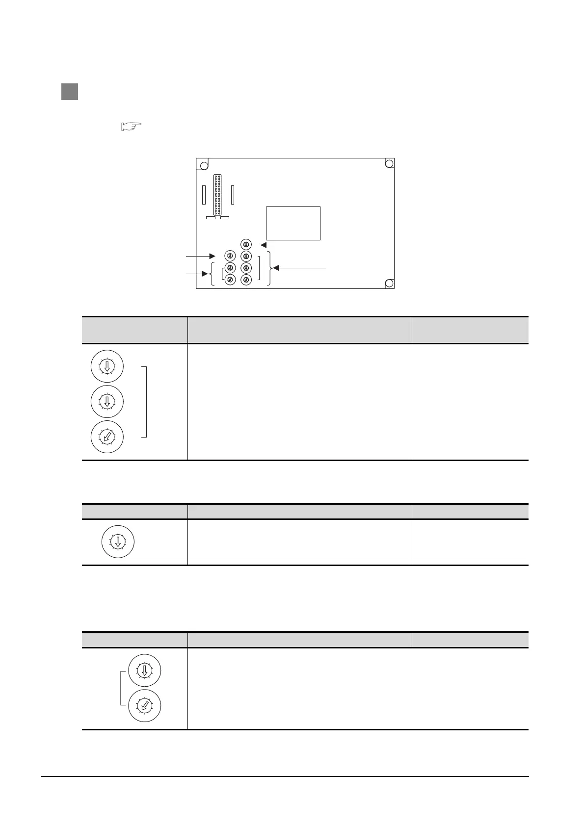
For details of each setting switch and LED, refer to the following manual.
GT15 MELSECNET/10 communication unit User’s Manual
(1) Network number setting switch
(2) Group number setting switch
*1 The GOT does not use the group number.
Specify "0".
(3) Station number setting switch
Network number setting
switch
Description Setting
Set the network No. of the MELSECNET/10 communication unit.
<Default: 001>
1 to 239
Group number setting switch Description Setting
Set the group No. of the MELSECNET/10 communication unit.
<Default: 0>
0: No group setting (fixed)
*1
Station number setting switch Description Setting
Set the station No. of the MELSECNET/10 communication unit.
Set to not duplicate other stations in the network.
<Default: 01>
1 to 64: GT15-75J71LP23-Z
1 to 32: GT15-75J71BR13-Z
8
0
7
F
6
E
5
D
4
C
3
B
2
A
1
9
MODE
5
0
6
1
7
2
8
3
9
4
5
0
6
1
7
2
8
3
9
4
STATION
No.
X10
X1
5
0
6
1
7
2
8
3
9
4
5
0
6
1
7
2
8
3
9
4
NETWORK
No.
X10
5
0
6
1
7
2
8
3
9
4
X100
X1
5
0
6
1
7
2
8
3
9
4
GROUP No.
RUN
PC
DUAL
SW.E
M/S.E
PRM.E
CRC
OVER
AB.IF
TIME
DATA
UNDER
LOOP
SD
RD
POWER
D.LINK
T.PASS
GOT R/W
CRC
OVER
AB.IF
TIME
DATA
UNDER
LOOP
SD
RD
E
R
R
O
R
E
R
R
O
R
F.LOOP
R.LOOP
GT15-75J71LP23-Z, GT15-75J71BR13-Z
(4)
(2)
(1)
(3)
5
0
6
1
7
2
8
3
9
4
5
0
6
1
7
2
8
3
9
4
NETWORK
No.
X10
5
0
6
1
7
2
8
3
9
4
X100
X1
5
0
6
1
7
2
8
3
9
4
GROUP No.
5
0
6
1
7
2
8
3
9
4
5
0
6
1
7
2
8
3
9
4
STATION
No.
X10
X1

 Loading...


