4 - 44
4.4 PLC Side Setting
4.4.2 Connecting serial communication module (QnA Series)
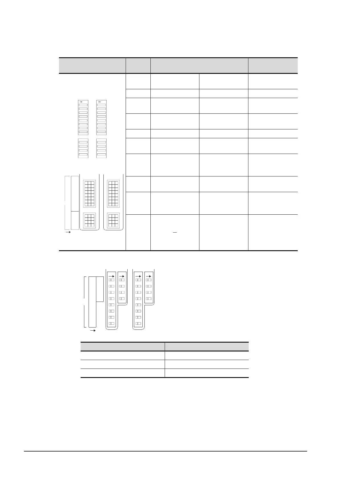
(2) Transmission specifications setting switch
*1 The following shows the layout of switches in the case of the following hardware versions for the module,
Switch settings and switch ON/OFF directions are the same.
Transmission specifications
setting switch
Setting
switch
Description Setting
AJ71QC24 (N) (-R2/R4)
A1SJ71QC24 (N) (-R2)
*1
SW01 Operation setting
Independent
operation
OFF
SW02 Data bit setting 8 bits ON
SW03
Parity bit enable/
disable setting
Enable ON
SW04
Even/odd parity
setting
Odd OFF
SW05 Stop bit setting 1 bit OFF
SW06
Sum check enable/
disable setting
Enable ON
SW07
Write during RUN
enable/disable
setting
Enable ON
SW08
Setting change
enable/disable
Disable (prohibit) OFF
SW09
to
SW12
Transmission speed
setting
(Consistent with the
GOT side
specifications.)
See (a)
SW13
to
SW15
The switch is located
on the left side of the
module.
(only on AJ71QC24N (-
R2/R4))
All OFF
Target unit Hardware version
A1SJ71QC24 Version E hardware or earlier
A1SJ71QC24-R2 Version D hardware or earlier
A1SJ71QC24N, A1SJ71QC24N-R2 Version A hardware
SW
01
02
03
04
05
06
07
08
09
10
11
12
ONON
ON
2
1
4
3
6
5
8
7
10
9
12
11
SW
1
8
2
3
4
5
6
7
9
10
11
12
SW
CH1/2
ON

 Loading...


