4.4 PLC Side Setting
4.4.2 Connecting serial communication module (QnA Series)
4 - 45
1
OVERVIEW
2
BUS CONNECTION
3
DIRECT CONNECTION
TO CPU
4
COMPUTER LINK
CONNECTION
5
MELSECNET/10
CONNECTION (PLC TO
PLC NETWORK)
6
CC-Link CONNECTION
(INTELLIGENT DEVICE
STATION)
7
CC-Link CONNECTION
(Via G4)
8
ETHERNET
CONNECTION
(a) Transmission speed setting (SW09 to SW12)
Set the transmission speed (SW09 to SW12) as follows.
The transmission speed setting must be consistent with that of the GOT side.
For how to set the GOT side transmission speed, refer to the following.
Section 4.3.3 Setting communication interface (Communication settings)
*1 Only transmission speeds available on the GOT side are shown.
*2 When the software version of AJ71QC24 (-R2/R4) and A1SJ71QC24 (-R2) is "L" or earlier, and when 2 devices
are connected to the two interfaces individually, make the setting so that the total transmission speed of the two
interfaces is within 19200bps.
When only one device is connected to either of the interfaces, a maximum transmission speed of 19200bps can
be set to the one where the device is connected. In this instance, set 300bps to the other side.
*3 When 2 devices are connected to the two interfaces individually in the case of AJ71QC24 (-R2/R4) and
A1SJ71QC24 (-R2), make the setting so that the total transmission speed of the two interfaces is within
115200bps.
When only one device is connected to either of the interfaces, a maximum transmission speed of 115200bps can
be set to the one where the device is connected. In this instance, set 300bps to the other side.
*4 This can be set only in the case of AJ71QC24N (-R2/R4) or A1SJ71QC24N (-R2).
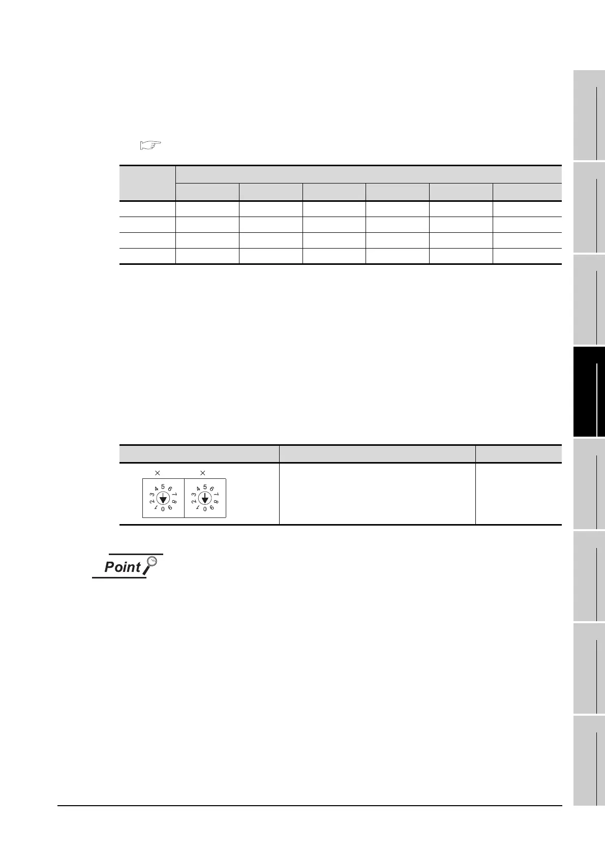
(3) Station number switch (for both CH1 and CH2)
*5 The station number switch in the figure is for the AJ71QC24 (N) (-R2/R4).
When the switch setting has been changed
Turn the PLC CPU OFF then ON again, or reset the PLC CPU.
Setting Switch
Transmission speed
*1*2*3
4800bps 9600bps 19200bps
38400bps
*4
57600bps
*4
115200bps
*4
SW09 OFF ON OFF ON OFF ON
SW10 OFF OFF ON ON ON ON
SW11 ON ON ON ON OFF OFF
SW12 OFF OFF OFF ON ON ON
Station number switch
*5
Description Setting
Set the station number of the serial communication
module to which an access is made from the GOT.
0
1
STATION
No.
10

 Loading...


