4.4 PLC Side Setting
4.4.3 Connecting computer link module
4 - 47
1
OVERVIEW
2
BUS CONNECTION
3
DIRECT CONNECTION
TO CPU
4
COMPUTER LINK
CONNECTION
5
MELSECNET/10
CONNECTION (PLC TO
PLC NETWORK)
6
CC-Link CONNECTION
(INTELLIGENT DEVICE
STATION)
7
CC-Link CONNECTION
(Via G4)
8
ETHERNET
CONNECTION
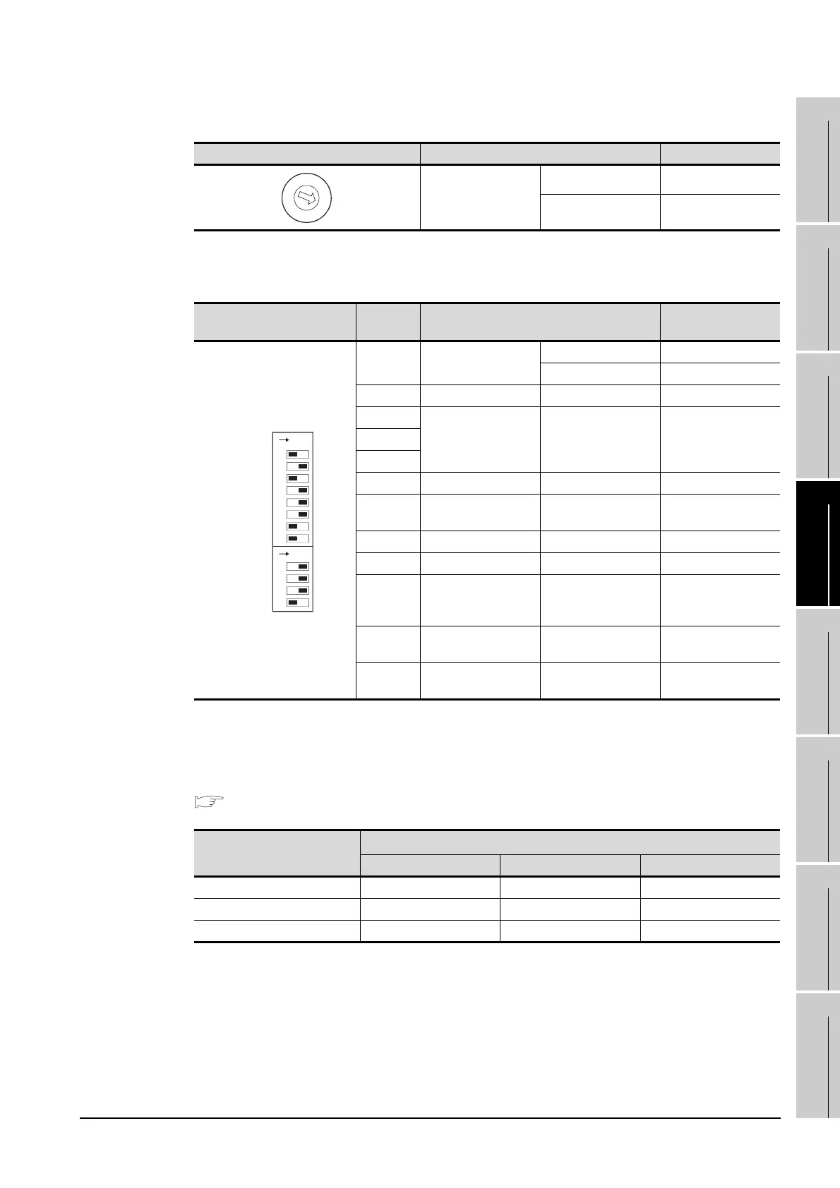
(1) Mode setting switch
(2) Transmission specifications switch
(a) AJ71UC24
• Transmission speed setting (SW13 to SW15)
Set the transmission speed (SW13 to SW15) as follows.
The transmission speed setting must be consistent with that of the GOT side.
For how to set the GOT side transmission speed, refer to the following.
Section 4.3.3 Setting communication interface (Communication settings)
*1 Only transmission speeds available on the GOT side are shown.
Mode setting switch Description Setting
Dedicated protocoltype
1
RS-232 connection 1
RS-422 connection 5
Transmission specifications
switch
Setting
switch
Description Setting
SW11 Main channel setting
RS-232 connection OFF
RS-422 connection ON
SW12 Data bit setting 8 bits ON
SW13
Transmission speed
setting
(Consistent with the
GOT side
specifications.)
See descriptions
below.
SW14
SW15
SW16 Parity bit setting Set ON
SW17
Even/odd parity
setting
Odd OFF
SW18 Stop bit setting 1 bit OFF
SW21 Sum check setting Set ON
SW22
Write during RUN
enabled/disabled
setting
Enabled ON
SW23
Computer link/
Multidrop selection
Computer link ON
SW24
Master station/
Local station setting
(Setting ignored) OFF
Setting switch
Transmission speed
*1
4800bps 9600bps 19200bps
SW13 OFF ON OFF
SW14 OFF OFF ON
SW15 ON ON ON
C
B
A
9
8
7
6
5
4
3
2
1
0
F
E
D
ON
SW11
SW12
SW13
SW14
SW15
SW16
SW17
SW18
SW21
SW22
SW23
SW24
ON

 Loading...


