4 - 48
4.4 PLC Side Setting
4.4.3 Connecting computer link module
(b) A1SJ71UC24-R2, A1SJ71UC24-PRF, A1SJ71C24-R2, A1SJ71C24-PRF
• Transmission speed setting (SW05 to SW07)
Set the transmission speed (SW05 to SW07) as follows.
The transmission speed setting must be consistent with that of the GOT side.
For how to set the GOT side transmission speed, refer to the following.
Section 4.3.3 Setting communication interface (Communication settings)
*1 Only transmission speeds available on the GOT side are shown.
(c) A1SJ71UC24-R4, A1SJ71C24-R4
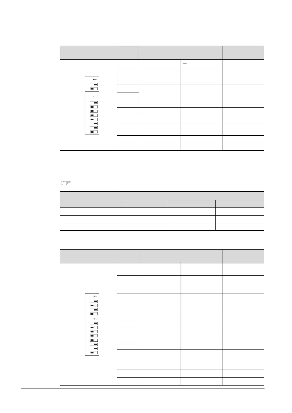
Transmission specifications
switch
Setting
switch
Description Setting
SW03 Unused OFF
SW04
Write during RUN
enabled/disabled
setting
Enabled ON
SW05
Transmission speed
setting
(Consistent with the
GOT side
specifications.)
See descriptions
below.
SW06
SW07
SW08 Data bit setting 8 bits ON
SW09 Parity bit setting set ON
SW10
Even/odd parity
setting
Odd OFF
SW11 Stop bit setting 1 bit OFF
SW12 Sum check setting Set ON
Setting switch
Transmission speed
*1
4800bps 9600bps 19200bps
SW05 OFF ON OFF
SW06 OFF OFF ON
SW07 ON ON ON
Transmission specifications
switch
Setting
switch
Description Setting
SW01
Master station/
Local station setting
(Setting ignored) OFF
SW02
Computer link/
multidrop link
selection
Computer link ON
SW03 Unused OFF
SW04
Write during RUN
enabled/disabled
setting
Enabled ON
SW05
Transmission speed
setting
(Consistent with the
GOT side
specifications.)
See descriptions
below.
SW06
SW07
SW08 Data bit setting 8 bits ON
SW09 Parity bit setting Set ON
SW10
Even /odd parity
setting
Odd OFF
SW11 Stop bit setting 1 bit OFF
SW12 Sum check setting Set ON
ON
03
04
05
06
07
08
09
10
11
12
ON
SW
ON
01
02
03
04
05
06
07
08
10
11
12
SW
09
ON

 Loading...


