4.4 PLC Side Setting
4.4.3 Connecting computer link module
4 - 51
1
OVERVIEW
2
BUS CONNECTION
3
DIRECT CONNECTION
TO CPU
4
COMPUTER LINK
CONNECTION
5
MELSECNET/10
CONNECTION (PLC TO
PLC NETWORK)
6
CC-Link CONNECTION
(INTELLIGENT DEVICE
STATION)
7
CC-Link CONNECTION
(Via G4)
8
ETHERNET
CONNECTION
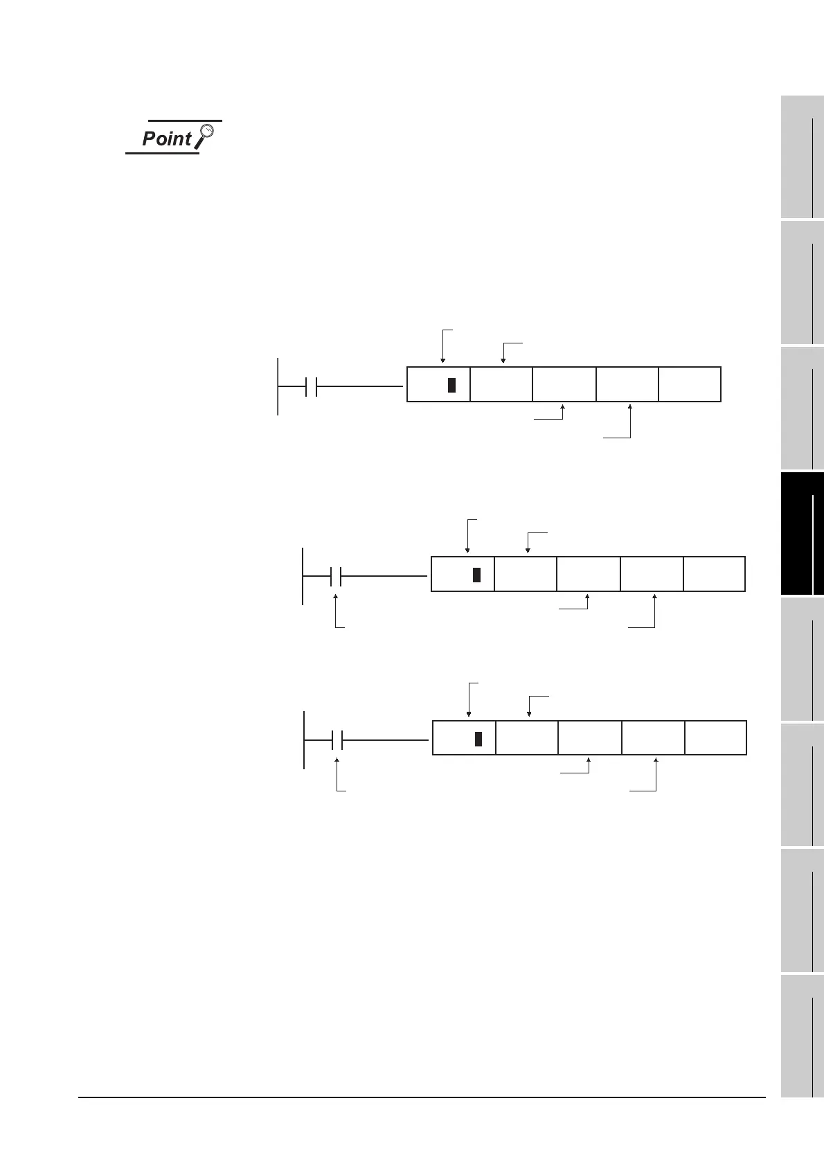
When connecting the GT11 and the computer link unit
When the GT11 and the computer link unit are connected via RS-232C, set the
buffer memory in the computer link unit using the sequence program so that CD
signals are not checked.
Examples of the CPU units equipped with built-in computer link are explained
below also.
(1) In the case of A computer link
Refer to the program example below in which the I/O signals of the computer link
unit are 80 to 9F (H).
(2) In the case of CPU equipped with built-in computer link
(a) A1SCPUC24-R2
(b) A2CCPUC2
X87
TO
Write to buffer memory
10B(H):CD terminal will be checked
K1:CD terminal will not be checked
Computer link unit connection point
H8 H10B K1 K1P
X0E7
TO
Write to buffer memory
10B(H):CD terminal will be checked
K1:CD terminal will be checked
Fixed values
Computer link unit connection point
(Fixed values)
H0E H10B K1 K1P
X1E7
TO
Write to buffer memory
10B(H):CD terminal will be checked
K1:CD terminal will not be checked
Fixed values
Computer link unit connection point
(Fixed values)
H1E H10B K1 K1
P

 Loading...


