5.2 Preparatory Procedures for Monitoring
5.2.3 Setting communication interface (Communication settings)
5 - 13
1
OVERVIEW
2
BUS CONNECTION
3
DIRECT CONNECTION
TO CPU
4
COMPUTER LINK
CONNECTION
5
MELSECNET/10
CONNECTION (PLC TO
PLC NETWORK)
6
CC-Link CONNECTION
(INTELLIGENT DEVICE
STATION)
7
CC-Link CONNECTION
(Via G4)
8
ETHERNET
CONNECTION
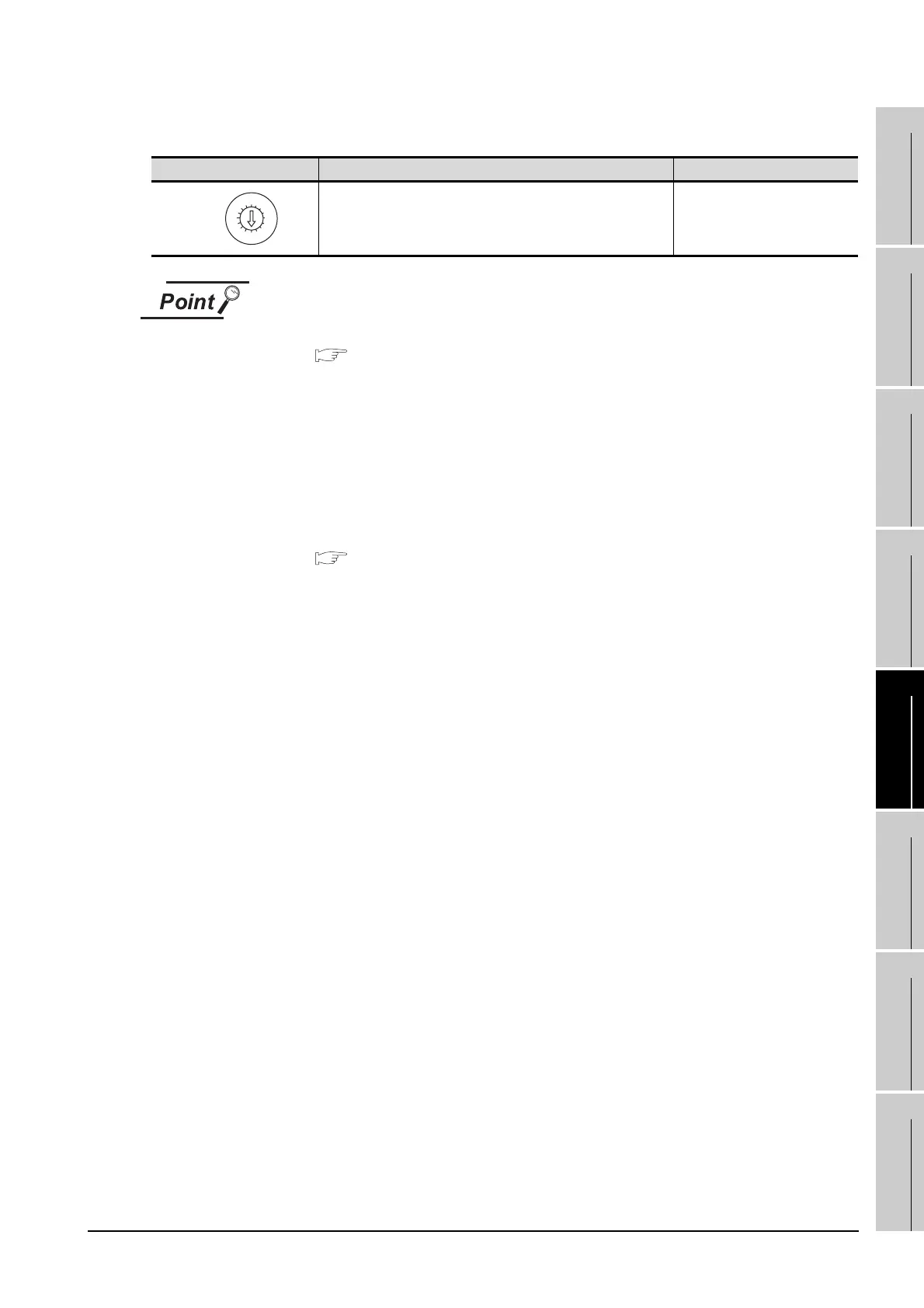
(4) Mode setting switch
(1) Switch setting example
For the switch setting example, refer to the following.
Section 5.3 PLC Side Setting
(2) When the switch setting is changed
When changing the switch setting after mounting the MELSECNET/10
communication unit to the GOT, reset the GOT.
(3) Self check test
Select "3" to "9" as the mode setting switch to provide a self check test of the
MELSECNET/10 communication unit.
For details, refer to the following manual.
GT15 MELSECNET/10 communication unit User's Manual
Mode setting switch Description Setting
On-line
<Default: 0>
0
8
0
7
F
6
E
5
D
4
C
3
B
2
A
1
9
MODE

 Loading...


