6.3 PLC Side Setting
6.3.3 Connecting to CC-Link module (A Series)
6 - 39
1
OVERVIEW
2
BUS CONNECTION
3
DIRECT CONNECTION
TO CPU
4
COMPUTER LINK
CONNECTION
5
MELSECNET/10
CONNECTION (PLC TO
PLC NETWORK)
6
CC-Link CONNECTION
(INTELLIGENT DEVICE
STATION)
7
CC-Link CONNECTION
(Via G4)
8
ETHERNET
CONNECTION
(2) Program condition (for FROM/TO instruction)
This program writes parameters to the buffer memory when PLC CPU status changes from STOP
to RUN and automatically starts the data link with FROM/TO instruction.
(a) I/O signal of CC-Link module
Control & Communication Link System Master/Local Module Type AJ61BT11/
A1SJ61BT11 User's Manual
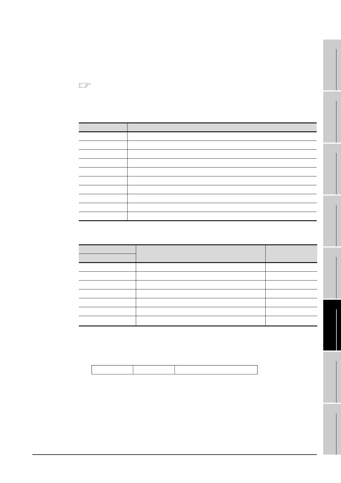
(b) Devices used by user
(c) Buffer memory settings used in the present example
*1 Details for the station data are shown below.
For 1) and 2), set according to the station number setting switch of the CC-Link communication unit and condition
setting switches (SW2).
For 3), the setting is fixed.
1) Station No. (set it according to the station number setting switch.)
01
H to 40H: Station No. 1 to Station No. 64
2) Number of stations occupied (set it according to the condition setting switches (SW2).)
1
H : Exclusive station 1
2
H : Exclusive station 2
3
H : Exclusive station 3
4
H : Exclusive station 4
3) Station type (2
H : Set it to intelligent device station.)
0
H : Remote I/O station
1
H : Remote device station
2
H : Intelligent device station (Incl. local station)
Device Application
M100, M101 Flag for parameter setting
M102, M103 Flag for data link startup
D0 Number of connected modules
D1 Number of retry
D2 No. of automatic return stations
D3 Operation specification in the case of CPU failure
D4 Reserved station specification (Station No. 1 to Station No. 16)
D5 Error invalid station specification (Station No. 1 to Station No. 16)
D6 Station data (first module)
D400 Error code in the case of data link startup failure
Buffer memory address
Item Setting
Decimal (Hexadecimal)
1 (1H) Number of connected modules 1 (1 module)
2 (2H) Number of retry 3 (3 times)
3 (3H) Number of automatic return stations 1 (1 station)
6 (6
H) Operation specification in the case of CPU failure 0 (stop)
16 (10
H) Reserved station specification (Station No. 1 to Station No. 16) 0 (No specification)
20 (14H) Error invalid station specification (Station No. 1 to Station No. 16) 0 (No specification)
32 (20H)
Station data (first module)
*1
2101H
b15 b12to b11 b8to b7 to b0
3) 2) 1)

 Loading...


