8 - 26
8.3 PLC Side Setting
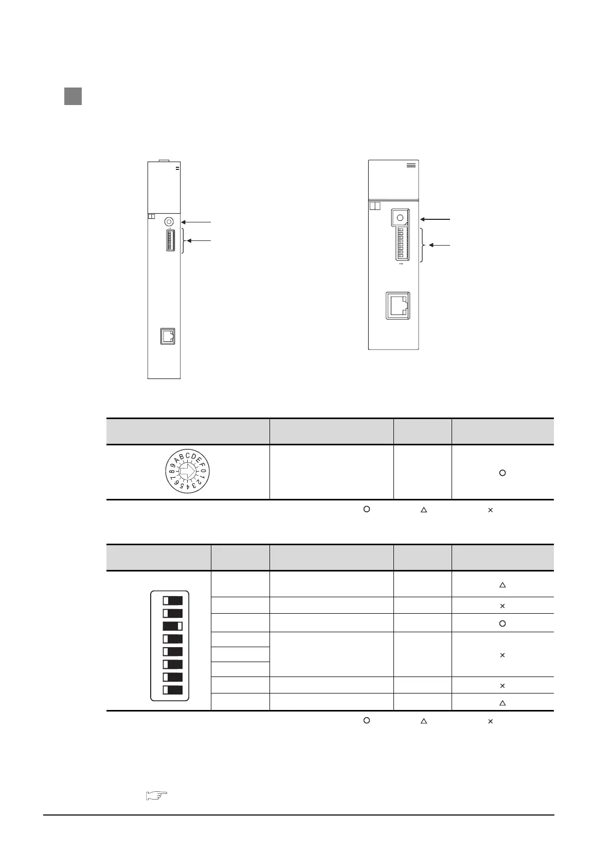
8.3.2 Connecting to Ethernet module (QnA Series)
2 Switch settings of Ethernet module
Set the operation mode setting switch and exchange condition setting switch.
*1 The figure of AJ71QE71N3-T and A1SJ71QE71N3-T.
(1) Operation mode setting switch
: Necessary : As necessary : Not necessary
(2) Exchange condition setting switch
: Necessary : As necessary : Not necessary
*2 Because port No. 5001 is fixed, these items operate at the following setting without relations to the setting given
here.
• Data code setting : [Binary code]
• Enable Write at RUN time : [Enable Write at RUN time] (Writing Data is applicable while running the PLC CPU.)
*3 In addition, communication is applicable while stopping the PLC CPU.
For the initial processing by using the initial request signal (Y19), refer to the following manual.
For QnA Ethernet Interface Module User's Manual
Operation mode setting switch Descriiption Setting
Setting necessity at GOT
connection
Online 0(fixes)
Exchange condition setting
switch
Setting switch Description Setting
Setting necessity at GOT
connection
SW1
Selection of line processing at
TCP timeout error
OFF
SW2 Data code setting *2 OFF(fixed)
SW3 Self start mode setting *3 ON
SW4
(Must not to be used) OFF(fixed)SW5
SW6
SW7 CPU exchange timing setting *2 OFF(fixed)
SW8 Initial timing setting OFF
10BASE-T
B
4
3
2
1
0
F
E
D
C
A
9
8
7
6
5
RUN BUF 1
BUF2
BUF3
BUF4
BUF5
BUF6
BUF7
BUF8
RDY
BSY
SW.ERR.
COM.ERR.
CPU R/W
TEST
TEST ERR.
A
J71QE71N3-T
ON
0:ONLINE
5:TEST4
4:TEST3
3:TEST2
2:TEST1
1:OFFLINE
MODE
SW8
SW7
SW6
SW5
SW4
SW3
SW2
SW1
(1)
(2)
ON
SW1
SW2
SW3
SW4
SW5
SW6
SW7
SW8
10BASE-T
A1SJ71QE71N3-T
4:TEST3
3:TEST2
2:TEST1
1:OFFLINE
0:ONLINE
5:TEST4
MODE
5
6
7
8
9
A
B
C
D
E
F
‚O
1
2
3
4
BSY
SW.ERR.
COM.ERR.
CPU R/W
TEST ERR.
TEST
RDY
RUN BUF1
BUF2
BUF3
BUF4
BUF5
BUF6
BUF7
BUF8
A
1SJ71QE71N3-T
A1SJ71QE71N3-T, A1SJ71QE71N-B5, A1SJ71QE71N-B2,
A1SJ71QE71N-T, A1SJ71QE71N-B5T,
A1SJ71QE71-B5, A1SJ71QE71-B2
J71QE71N3-T, AJ71QE71N-B5, AJ71QE71N-B2,
J71QE71N-T, AJ71QE71N-B5T,
J71QE71, AJ71QE71-B5
(1)
(2)
*1
*1
SW1
SW2
SW3
SW4
SW5
SW6
SW7
SW8
OFF ON

 Loading...


