8.3 PLC Side Setting
8.3.3 Connecting to Ethernet module (A Series)
8 - 33
1
OVERVIEW
2
BUS CONNECTION
3
DIRECT CONNECTION
TO CPU
4
COMPUTER LINK
CONNECTION
5
MELSECNET/10
CONNECTION (PLC TO
PLC NETWORK)
6
CC-Link CONNECTION
(INTELLIGENT DEVICE
STATION)
7
CC-Link CONNECTION
(Via G4)
8
ETHERNET
CONNECTION
(c) Settings of buffer memory used in the following example
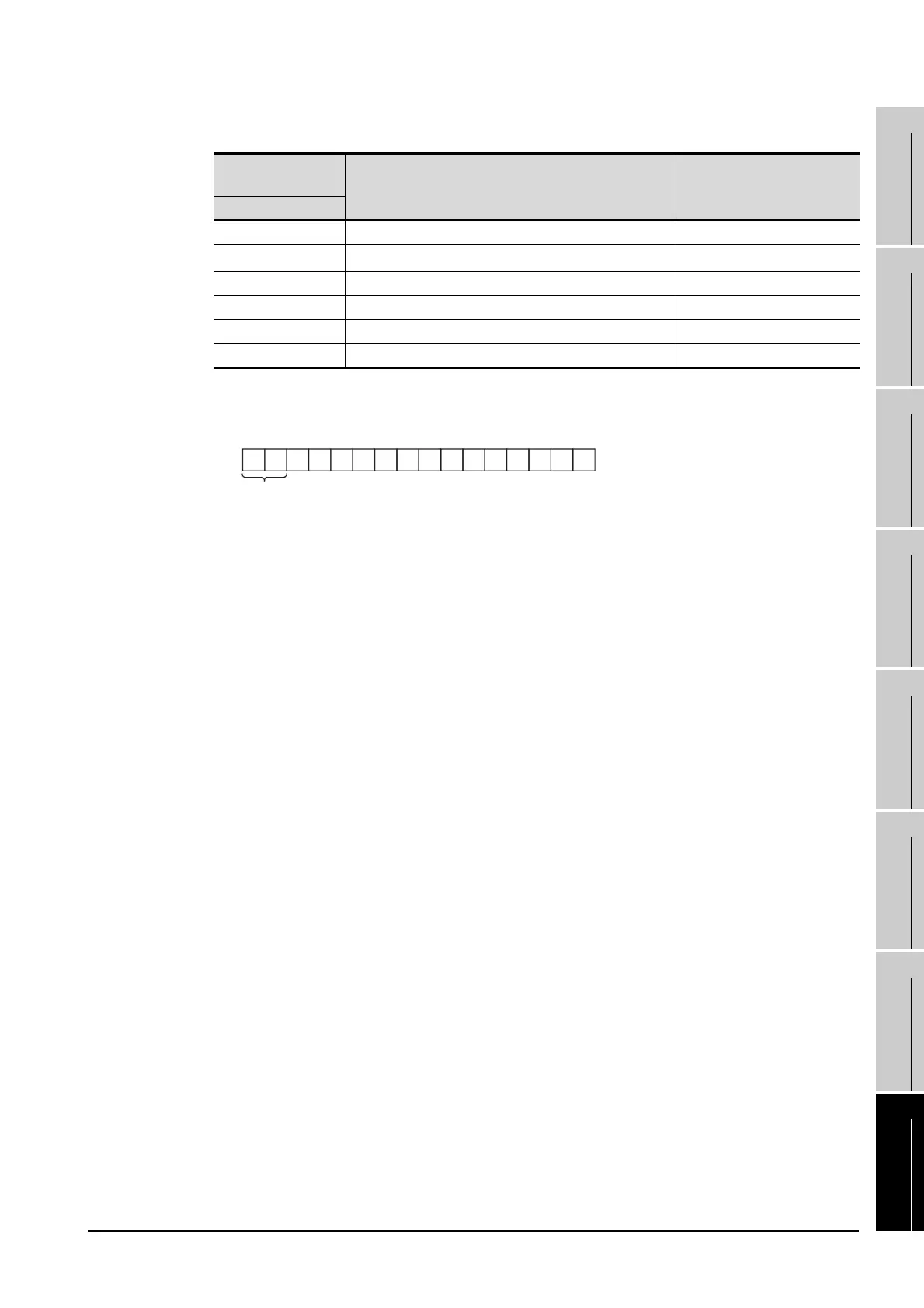
*1 The details of the application setting are shown below.
Settings 1), 2) and 3) can be changed by the user.
4), 5) and 6) are fixed.
1) Fixed buffer application
0: For sending; no exchange
1: For receiving
2) Existence check
0: No
1: Yes
3) Pairing open
0: No
1: Yes
4) Communication format (Set to "1" (UDP/IP).)
0: TCP/IP
1: UDP/IP
5) Fixed buffer exchange (Set to "0" (With procedure).)
0: With procedure
1: Without procedure
6) Open method (Set to "00" (Active, UDP/IP).
00: Active, UDP/IP
10: Unpassive
11: Fullpassive
Buffer memory
address
Item Setting
Dec (Hex)
0 to 1 (0 to 1H) IP address of Ethernet module C0A80013H(192.168.0.19)
16 (10H)
Application setting
*1
100H
24 (18H) Port No. of Ethernet module 5001
25 to 26 (19 to 1AH) IP address of GOT FFFFFFFFH
27 (1BH) Port No. of GOT FFFFH (fixed)
80 (50H) Initial fault code -
b15
0
b14
0
b13
0
b12
0
b11
0
b10
0
b9
0
b8
1
b7
0
b6
0
b5
0
b4
0
b3
0
b2
0
b1
0
b0
0
1)2)3)4)5)
6)

 Loading...


