1.2 Overall System Configurations
1 - 9
1
OVERVIEW
2
BUS CONNECTION
3
DIRECT CONNECTION
TO CPU
4
COMPUTER LINK
CONNECTION
5
MELSECNET/10
CONNECTION (PLC TO
PLC NETWORK)
6
CC-Link CONNECTION
(INTELLIGENT DEVICE
STATION)
7
CC-Link CONNECTION
(Via G4)
8
ETHERNET
CONNECTION
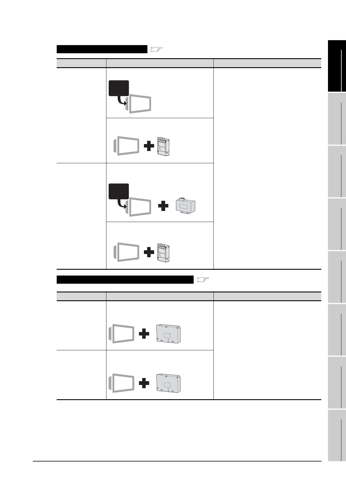
Computer link connection
( Chapter 4)
Communication Type Communication Interface on GOT Side Connected to
RS-232
communication
Built in GT15 body Serial communication module
• QCPU (Q mode)
•QnACPU
• Motion controller CPU (Q Series)
• Remote I/O station in the MELSECNET/H
network system
Computer link module
• QCPU (A mode)
•QnACPU
•ACPU
• Motion controller CPU (A Series)
RS-232 Communication Unit
• GT15-RS2-9P
RS-422
communication
RS-422 conversion unit
• GT15-RS2T4-9P
RS-422/485 Communication Unit
• GT15-RS4-9S
MELSECNET/10 connection (PLC to PLC network)
( Chapter 5)
Communication Type Communication Interface on GOT Side Connected to
Optical loop
MELSECNET/10 communication unit
• GT15-75J71LP23-Z
MELSECNET/H network module
• QCPU (Q mode)
• Motion controller CPU (Q Series)
MELSECNET/10 network module
• QCPU (A mode)
• QnACPU
• ACPU
• Motion controller CPU (A Series)
Coaxial bus
MELSECNET/10 communication unit
• GT15-75J71BR13-Z
RS-232
RS-232
 Loading...


