16 - 2
16.1 System Configuration
16.1.1 Connecting to FA-M3
16.1 System Configuration
Select a system configuration suitable for your application.
Conventions used in this section
Numbers (e.g. ) of System configuration and connection conditions correspond
to the numbers (e.g. ) of System equipment.
Use these numbers as references when confirming models and applications.
16.1.1 Connecting to FA-M3
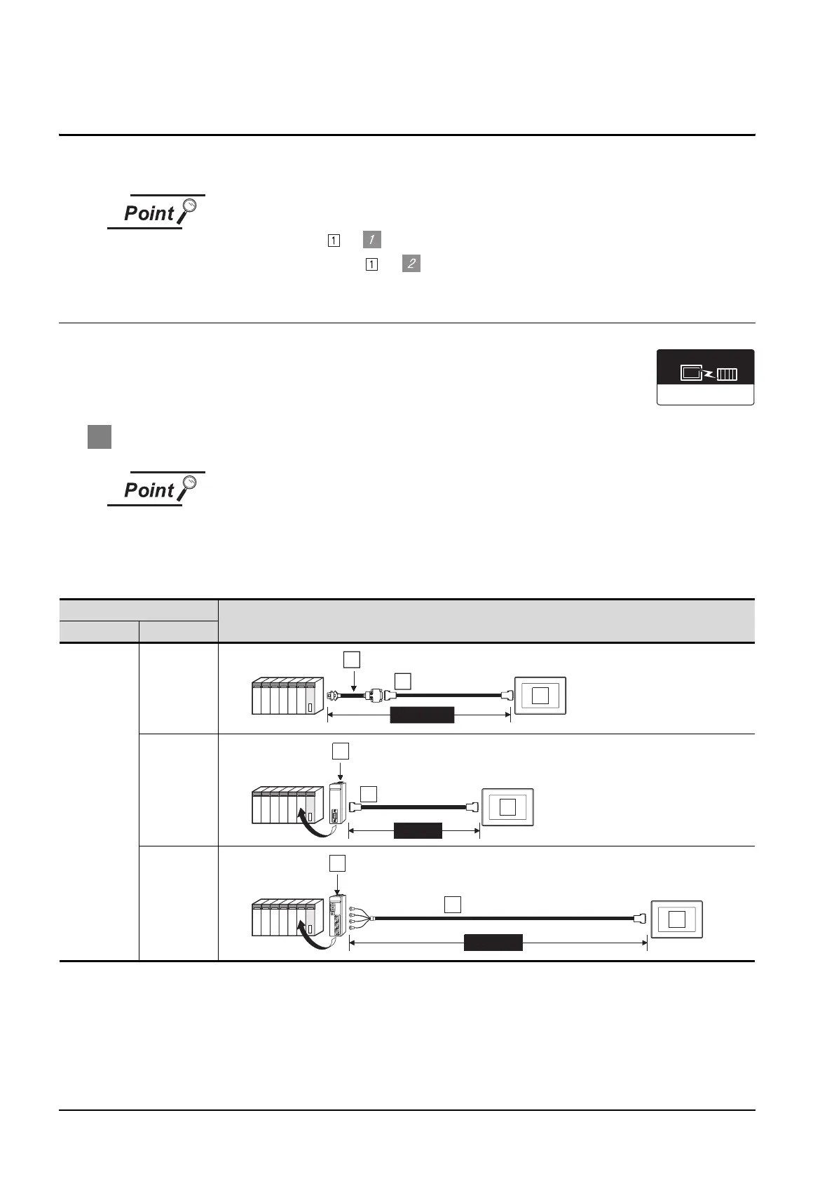
1 System configuration and connection conditions
(1) When the CPU port/D-Sub 9-pin conversion cable is used for connection to the
programming tool connector, the GOT cannot be connected to the following PLCs.
F3SP10, F3SP20, F3SP30, F3SP36
(2) Since the F3SP10 is not compatible with the PC link module (F3LC11-2N), RS-
422 connection is not available for it.
*1 This includes the length of the CPU port/D-Sub 9-pin conversion cable.
Connection conditions
System configuration
No. of GOTs Distance
1
15m or less
15m or less
1200m or less
Communication driver
YOKOGAWA FA500/FA-M3
RS-232 cable 1)
6
CPU port/D-Sub 9-pin conversion cable
5
MAX15m
*1
1
3
7
MAX15m
1
PC link mo dule
RS-232 cable 2)
PC link module
4
RS-422 cable 1)
8
MAX1200m
2

 Loading...


