16 - 8
16.2 Connection Cable
16.2.1 RS-232 cable
16.2.1 RS-232 cable
The following shows the connection diagrams and connector specifications of the RS-232 cable used for
connecting the GOT to a PLC.
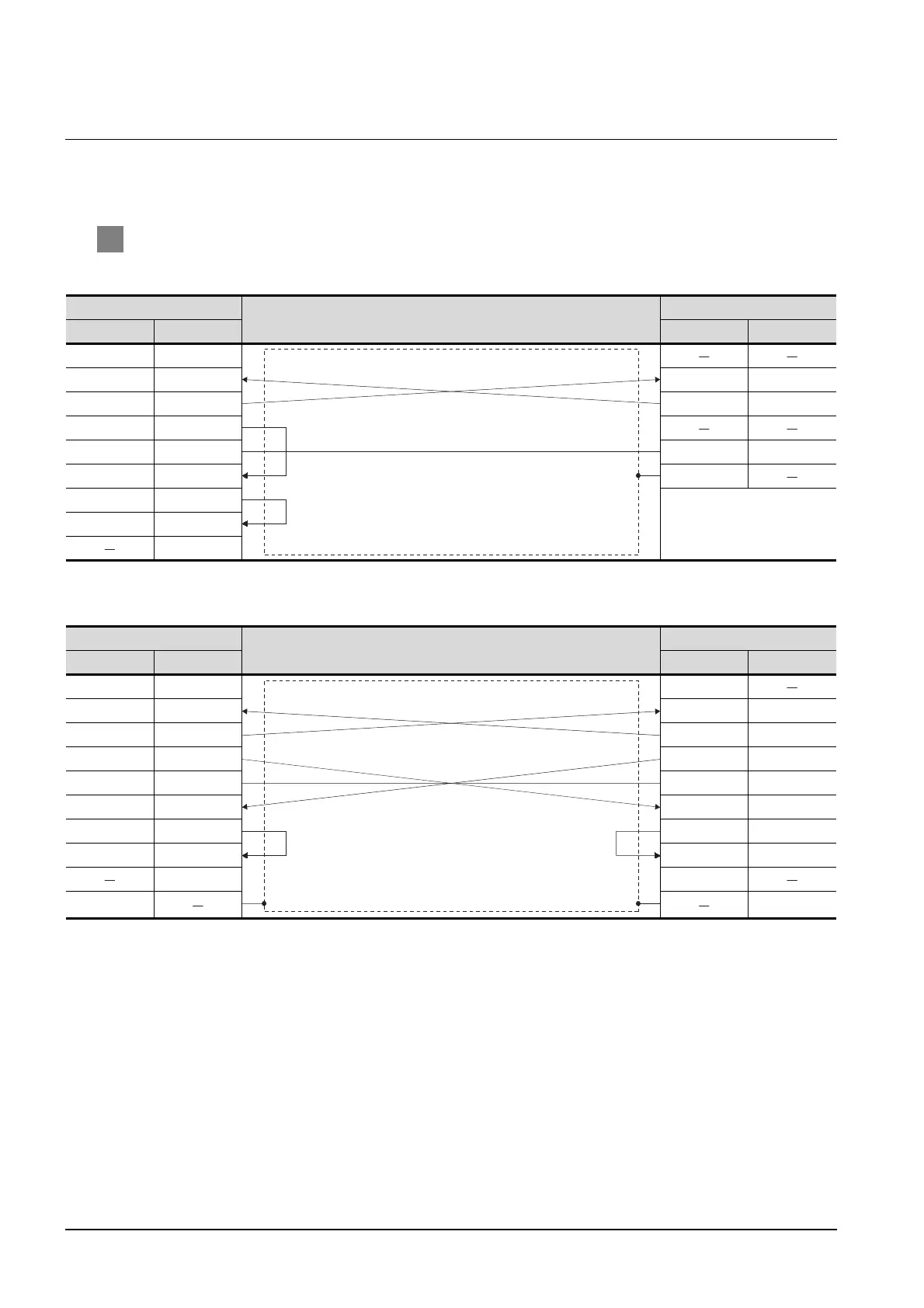
1 Connection diagram
(1) RS-232 cable 1)
*1 GT15:CD, GT11:NC
(2) RS-232 cable 2)
*2 GT15: CD, GT11: NC
*3 Connect the shield to the housing of the connectors on both the GOT and YOKOGAWA product sides.
GOT side
Cable connection and signal direction
YOKOGAWA product side
Signal name Pin No. Pin No. Signal name
CD/NC
*1
1
RD(RXD) 2 2RD
SD(TXD) 3 3SD
ER(DTR) 4
SG 5 5SG
DR(DSR) 6 SHIELD
RS(RTS) 7
CS(CTS) 8
9
GOT side
Cable connection and signal direction
YOKOGAWA product side
Signal name Pin No. Pin No. Signal name
CD/NC
*2
1 1
RD(RXD) 2 2RD
SD(TXD) 3 3SD
ER(DTR) 4 4ER
SG 5 5SG
DR(DSR) 6 6DR
RS(RTS) 7 7RS
CS(CTS) 8 8CS
9 9
Shell
*3
Shell
*3

 Loading...


