19.4 Device Data Area
19.4.1 D devices
19 - 13
17
CONNECTION TO
ALLEN-BRADLEY PLC
18
CONNECTION TO
SIEMENS PLC
19
MICROCOMPUTER
CONNECTION
20
CONNECTION TO OMRON
TEMPERATURE
CONTROLLER
21
CONNECTION TO
YAMATAKE TEMPERATURE
CONTROLLER
22
CONNECTION TO RKC
TEMPERATURE
CONTROLLER
23
CONNECTION TO
FREQROL SERIES
INVERTER
24
SERVO AMPLIFIER
CONNECTION
(from previous page)
*1 After writing data, the interrupt is output within a period of 1 to 10ms.
*2 When data are written to D13 and D14 from the host side, interrupt output is not performed.
(1) About the side where virtual devices are set
System: Set on the system side.
User: Set on the user side (by sending request messages from host or
using the touch switches, etc. on the GOT).
(2) About interrupt output (D13, D14)
• To disable the interrupt output, turn ON SM52 (interrupt code output disable
flag). ( Section 19.4.6 SM devices)
• To enable the interrupt output, set 8 bits to the data length at "Communication
Detail Settings". ( Section 19.6.3 Setting communication interface
(Communication settings))
• When "7 bits" is set, the MSB (8th bit) is ignored. (Example: FF
H 7FH)
Address Description Set side
D13
Interrupt output
When data are written to D13 and D14 from a GOT touch switch, for example, the data of D13 and
D14 are transmitted (interrupt output) to the host side.
*1 *2
The data amount (the number of bytes) to be interrupt-output is set at "Interrupt Data Byte" in
"Communication Detail Settings". ( Section 19.6.3 Setting communication interface
(Communication settings))
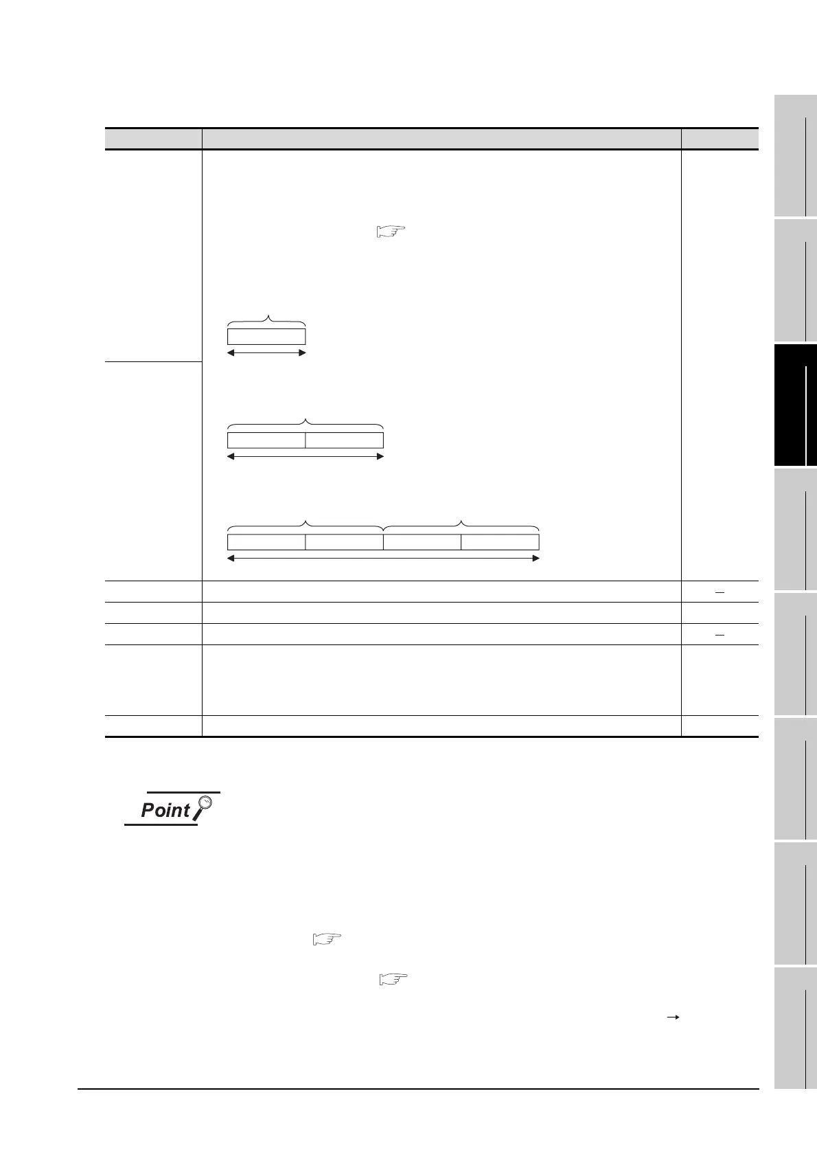
• Output value when 1 is set to "Interrupt Data Byte" in "Communication Detail Settings"
• Output value when 2 is set to "Interrupt Data Byte" in "Communication Detail Settings"
• Output value when 4 is set to "Interrupt Data Byte" in "Communication Detail Settings"
User
D14
D15 to 19 Unused
D20 to 2031 User area User
D2032 to 2034 Unused
D2035
1-second binary counter
The counter is incremented at 1-second intervals after the GOT is turned ON.
(The time elapsed after the GOT is turned ON is stored in 1-second units.) Data are stored in binary
format.
System
D2036 to 4095 User area User
D13
Lower 8 bits
1 byte
D13
Upper 8 bits Lower 8 bits
2 bytes
Upper 8 bits
D14 D13
Upper 8 bitsLower 8 bits Lower 8 bits
4Byte
 Loading...


