19 - 62
19.5 Message Formats
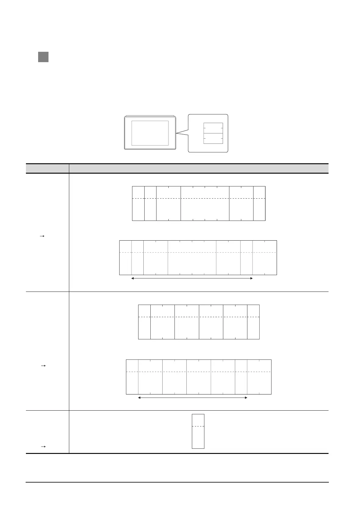
19.5.7 Formats 14, 15 (GOT-F900 series microcomputer connection)
3 Message format
(1) Batch read (0) command (w/out station No.), batch read (A) command (w/station No.)
(a) When reading word device
The following shows an example of reading four bytes of virtual devices R100 to R101 from the
GOT at station No.15.
(Assuming that R100="3D21
H" and R101="3604H" are stored.)
Item Message format
Request message
(host GOT)
(format 14: GOT-F900 series microcomputer connection (format 1))
(format 15: GOT-F900 series microcomputer connection (format 2))
Response
message during
normal
communication
(GOT host)
(format 14: GOT-F900 series microcomputer connection (format 1))
(format 15: GOT-F900 series microcomputer connection (format 2))
Response
message during
faulty
communication
(GOT host)
R100
R101
3D21H
3604H
02H
STX
0D
H
CR
(H) (L)
Station No.
15
31
H 35H
(H) (L)
Address
0
30
H
––
0
30
H
8
38
H
(H) (L)
Number
of bytes
04
30
H 34H
A
41
H
C
43
H
Com-
mand
Sum check is performed in this range.
02
H
STX
03H
ET X
(H) (L)
E9
45
H 39H
Sum
Check
(H) (L)
Station No.
15
31
H 35H
(H) (L)
Address
0
30
H
––
0
30
H
8
38
H
(H) (L)
Number of
bytes
04
30
H 34H
A
41
H
C
43
H
Com-
mand
02H
STX
0D
H
CR
(H)
Data 1
(R100 upper)
3
33
H
(L)
D
44
H
(H)
Data 2
(R100 lower)
2
32
H
(L)
1
31
H
(H)
Data 3
(R101 upper)
3
33
H
(L)
6
36
H
(H)
Data 4
(R101 lower)
0
30
H
(L)
4
34
H
Sum check is performed in this range.
02
H
STX
03
H
ETX
(H) (L)
A
41
H
Sum
Check
A
41
H
(H)
Data 1
(R100 upper)
3
33
H
(L)
D
44
H
(H)
Data 2
(R100 lower)
2
32
H
(L)
1
31
H
(H)
Data 3
(R101 upper)
3
33
H
(L)
6
36
H
(H)
Data 4
(R101 lower)
0
30
H
(L)
4
34
H
15H
NAK

 Loading...


