19.5 Message Formats
19.5.7 Formats 14, 15 (GOT-F900 series microcomputer connection)
19 - 61
17
CONNECTION TO
ALLEN-BRADLEY PLC
18
CONNECTION TO
SIEMENS PLC
19
MICROCOMPUTER
CONNECTION
20
CONNECTION TO OMRON
TEMPERATURE
CONTROLLER
21
CONNECTION TO
YAMATAKE TEMPERATURE
CONTROLLER
22
CONNECTION TO RKC
TEMPERATURE
CONTROLLER
23
CONNECTION TO
FREQROL SERIES
INVERTER
24
SERVO AMPLIFIER
CONNECTION
(6) Write specification
Specifies how to change the data of the specified address by bit pattern.
(Setting range: 0 to 3)
Data notated in decimal is converted to a 1-digit ASCII code (Hex) and transmitted.
(3) Multi-point write in bit units (3) command (w/out station No.), multi-point write in bit
units (D) command (w/ station No.)
(7) Number of bytes
Specifies the number of bytes of the device data to be batch read/written. (Setting range: 0 to FF
H)
Data notated in Hex is converted to a 2-digit ASCII code (Hex) and transmitted from the upper digit.
(8) Number of points
Specifies the number of device data to be written to multiple points in bit units. (Setting range: 0 to
70)
Data notated in decimal is converted to a 2-digit ASCII code (Hex) and transmitted from the upper
digit
(9) Year, month, day, hour, minute, second and day of the week data
Specifies year, month, day, hour, minute, second and day of the week to be read/set to the clock
data of the GOT.
Data notated in decimal is converted to a 2-digit ASCII code (Hex) and transmitted from the upper
digit.
(5) Read clock data (6) command (w/out station No.), read clock data (G) command
(w/station No.)
(6) Set clock data (5) command (w/out station No.), set clock data (F) command (w/
station No.)
(10) Data
Specifies the data to read from/write to the specified device data. (word unit)
Data notated in Hex is converted to a 4-digit ASCII code (Hex) and transmitted from the upper digit.
(11) Write data
Specifies the data to write to the specified device data.
Data notated in Hex is converted to a 2-digit ASCII code (Hex) and transmitted from the upper digit.
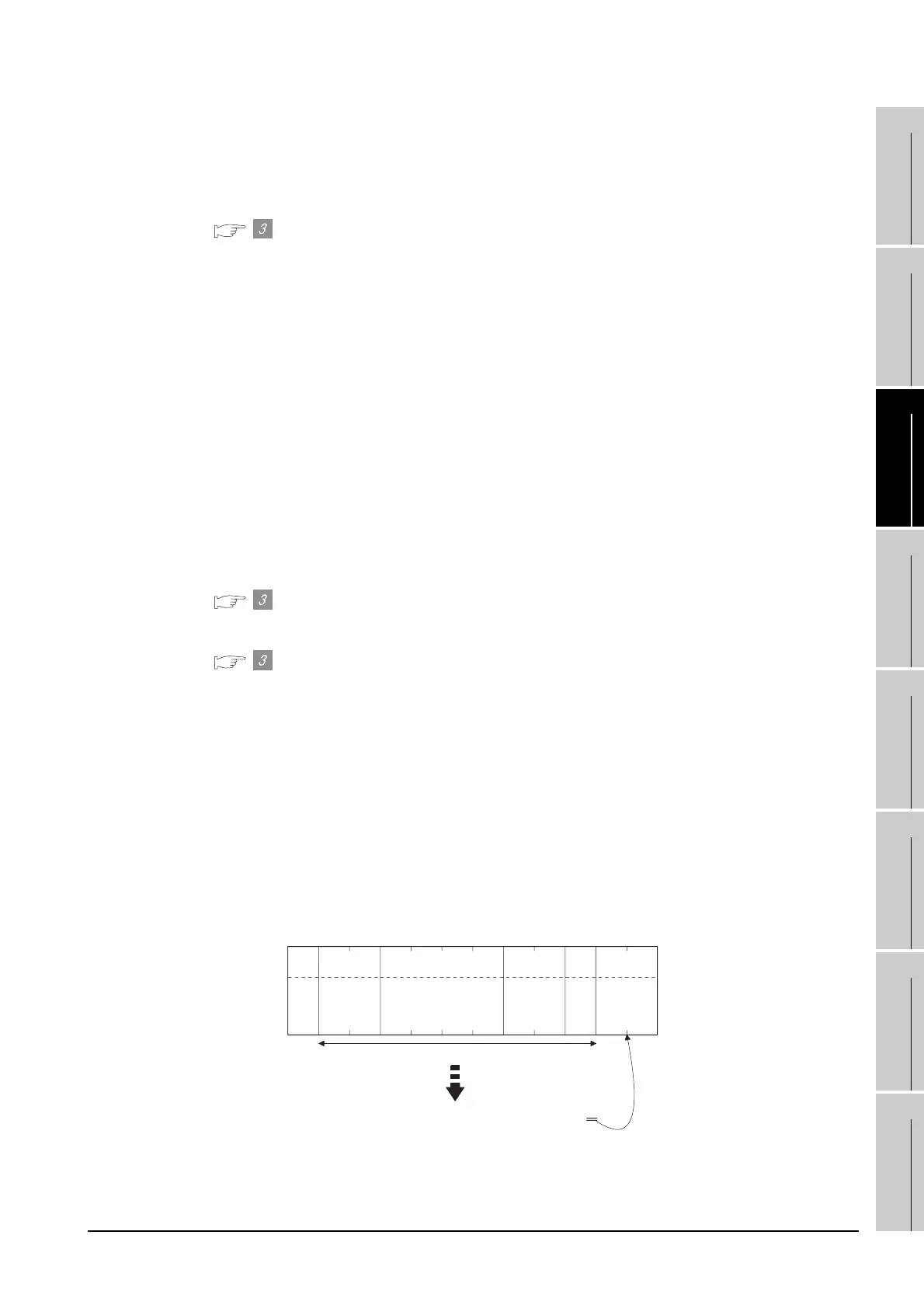
(12) Sum check code (for format 15: GOT-F900 series microcomputer connection (format 2) only)
The sum check code is obtained by converting the lower 1 byte (8 bits) of the result (sum), after
having added the sum check target data as binary data, to 2-digit ASCII code (Hex).
Sum check is performed in this range.
02
H
STX
03
H
ETX
(H) (L)
BC
42
H 43H
Sum
Check
(H) (L)
Command
RD
52
H 44H
(H) (L)
Address
01
30
H 31H
––
0
30
H
0
30
H
(H) (L)
Number of
points
02
30
H 32H
52H + 44H + 30H + 31H + 30H + 30H + 30H + 32H + 03H = 1BCH

 Loading...


