2.2 Preparatory Procedures for Monitoring
2.2.3 Setting communication interface (Communication settings)
2 - 31
1
OVERVIEW
2
BUS CONNECTION
3
DIRECT CONNECTION
TO CPU
4
COMPUTER LINK
CONNECTION
5
MELSECNET/10
CONNECTION (PLC TO
PLC NETWORK)
6
CC-Link CONNECTION
(INTELLIGENT DEVICE
STATION)
7
CC-Link CONNECTION
(Via G4)
8
ETHERNET
CONNECTION
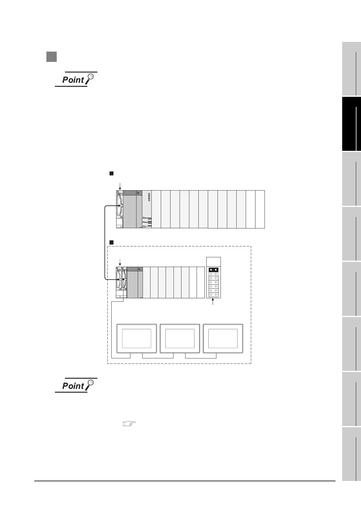
3 Setting Stage No. and Slot No.
Before setting Stage No. and Slot No.
The PLC CPU recognizes the GOT as follows.
• QCPU (Q mode) : Intelligent function module of 16 I/O points
• Other than QCPU (Q mode) : Intelligent function module of 32 I/O points
At the [Communication Detail Settings], assign the GOT to an empty I/O slot on the
PLC CPU.
(1) When connecting to QCPU (Q mode)
Set an additional stage (16 points x 10 slots) for GOT connection, and assign a GOT to one of the
I/O slots.
(The GOT cannot be assigned to empty slots of the main base unit or extension base unit.)
When using the bus extension connector box
Set the Stage No. switch on the bus extension connector box to the same Stage No.
as the GOT.
For setting details, refer to the following manual:
A9GT-QCNB Bus Extension Connector Box User's Manual
Q312B
Q68B
Main base unit
Stage No. :2
Slot No. :0
Stage No. :2
Slot No. :1
Stage No. :2
Slot No. :2
Extension base unit
Stage No. setting
connector
Extension
stage 1
Empty
Empty
Empty
Empty

 Loading...


