22 - 12
22.2 Connection Cable
22.2.2 RS-422 cable
22.2.2 RS-422 cable
The following shows the connection diagrams and connector specifications of the RS-422 cable used for
connecting the GOT to a temperature controller.
Differences in polarity between GOT and RKC products
The polarity of poles A and B in signal names is reversed between GOT and RKC
products.
Connect a cable according to the following connection diagrams.
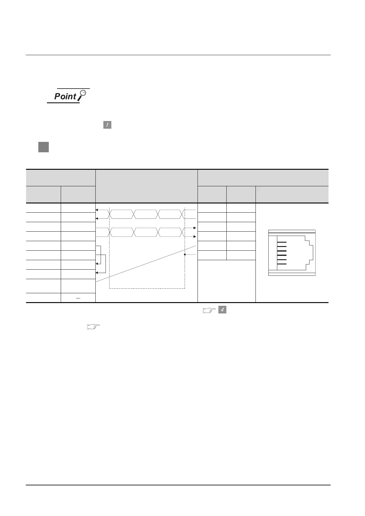
1 Connection diagram
(1) RS-422 cable 1)
*1 Set the terminating resistor of GOT side to “Disable”.( Connecting terminating resistors)
*2 For details of the pin assignment, refer to the following manual.
User's Manual for the RKC temperature controller
GOT side
*1
Cable connection and signal direction
RKC product side
(Modular connector)
Signal name Pin No. Pin No.
Signal
name
Pin assignment
*2
RDA 2 4 T(B)
RDB 7 5 T(A)
SDA 1 2 R(B)
SDB 6 1 R(A)
RSA 3 3 SG
RSB 8 6 SG
CSA 4
CSB 9
SG 5
FG
SG
T(A)
T(B)
SG
R(B)
R(A)
6
5
4
3
2
1
 Loading...


