XtraDrive User Manual Chapter 5: Parameter Settings and Functions
5-76
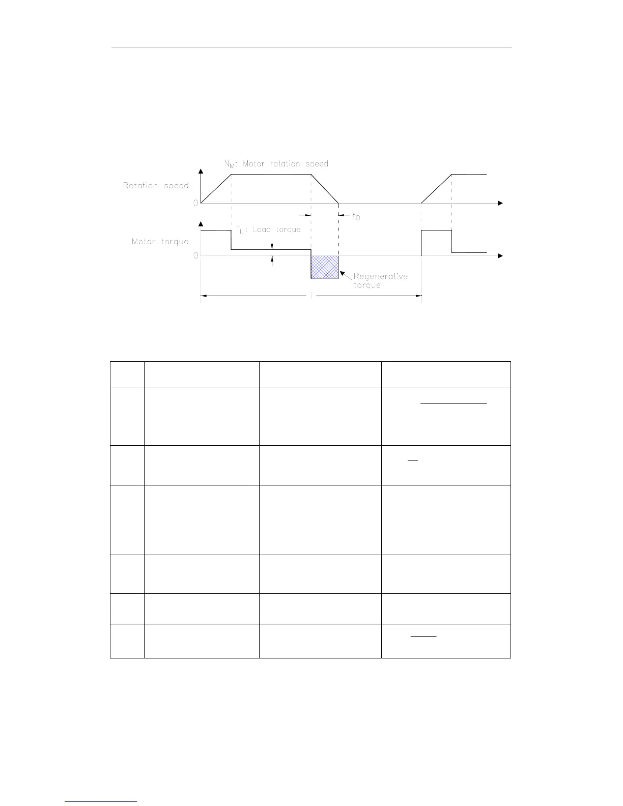
Regenerative Energy Calculation Method
This section shows the procedure for calculating the regenerative
resistor capacity when acceleration and deceleration operation is as
shown in the following diagram.
Calculation Procedure
The procedure for calculating the capacity is as follows:
Step
Procedure
Units
[in. (mm)]
Equation
1
Find the rotational energy
of the servo system (E
S
).
E
S
= [Joules] = [J]=
[ oz·in·s
2
(kg·m
2
·s
2
)]
J
L
= J
M
= J
N
M
= rpm
E
S
=
182
Nx J J
2
MML
+
Where: N
M
= Motor speed
J
L
= Load Inertia
J
M
= Motor Inertia
2
Find the energy consumed
by load system loss (E
L
)
during the deceleration
period (t
D
).
τ
L
= oz·in (N·m)
E
L
= Joules = J
N
M
= rpm
t
D
= s
E
L
=
60
π
(N
M
x τ
L
x t
D
)
Where: τ
L
= Motor torque
3
Calculate the energy lost
(E
M
) from servomotor
winding resistance.
t
D
= s = deceleration stopping
time
E
M
= Joules = J
E
M
= ( Value from the
“Servomotor Winding
Resistance Loss” graph below)
x t
D
4
Calculate the servo
amplifier energy (E
C
) that
can be absorbed.
E
C
= Joules = J
E
C
= Value from the
“Absorbable Servo Amplifier
Energy” graph below.
5
Find the energy consumed
by the regenerative resistor
(E
K
).
E
K
= E
S
=E
L
=E
M
= E
C
=
Joules = J
E
K
= E
S
— ( E
L
+E
M
+ E
C
)
6
Calculate the required
regenerative resistor
capacity (W
K
).
W
K
= W
E
K
= Joules = J
T = s
W
K
=
Tx 2.0
E
K
Where: T = Time
Note: The “0.2” in the equation for calculating W
K
is the value for when the regenerative resistor’s utilized
load ratio is 20%.
If the previous calculation determines that the amount of regenerative
power (W
Wk
) that can be processed by the built-in resistor is not
exceeded, then an external regenerative resistor is not required.