Home
Polaris
Utility Vehicle
2015 RZR 900
Polaris 2015 RZR 900 Service Manual
5
of 1
of 1 rating
457 pages
Give review
Manual
Specs
To Next Page
To Next Page
To Previous Page
To Previous Page
Loading...
3.18
9925723
R01
-
2015
RZR
900
Service
Manual
©
Copyright
2014
Polaris
Industries
Inc.
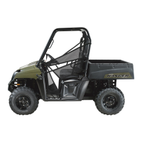
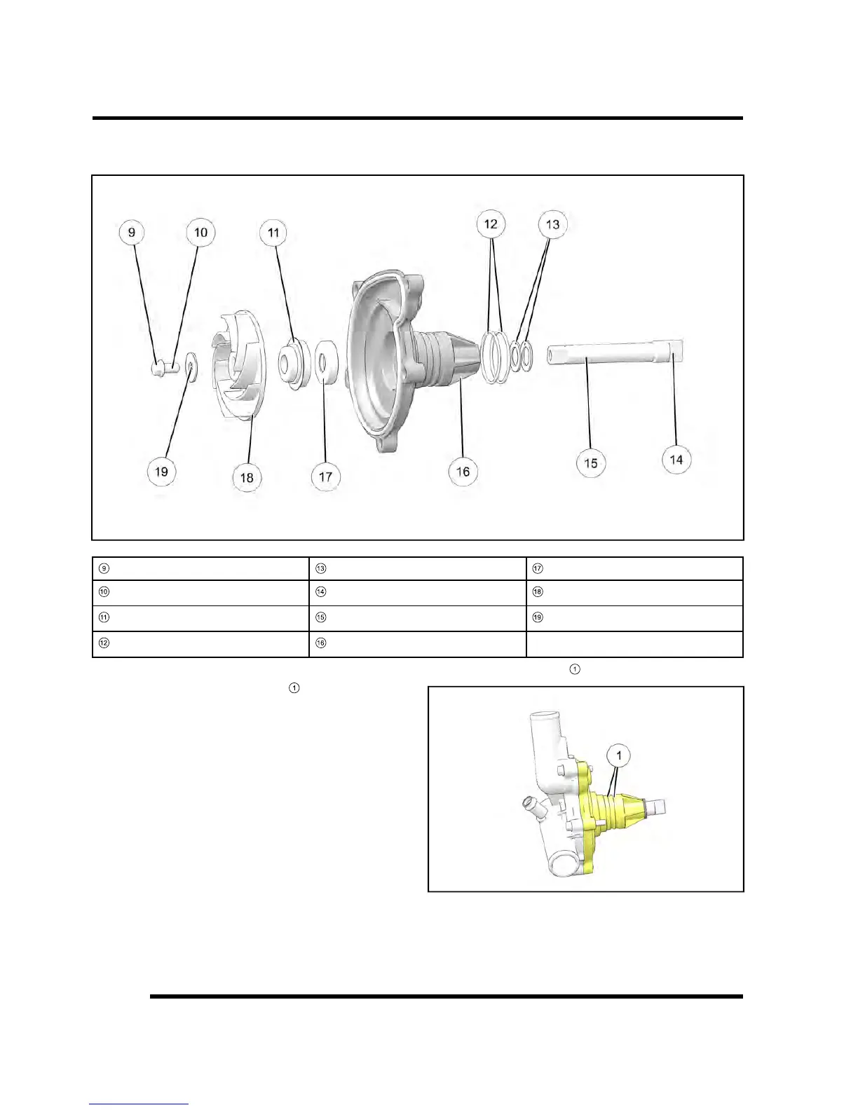
20.
Install
two
new
water
pump
o-rings
and
lubricate
them
with
clean
engine
oil.
21.
Install
water
pump
assembly
into
the
engine.
(see
Chapter
3
–
W
ater
Pump
Installation,
page
3.18)
9
Bolt
1
3
W
ashers
1
7
Oil
Seal
1
0
Loctite
204
1
4
Drive
T
ab
1
8
Impeller
1
1
Mechanical
Seal
1
5
W
ater
Pump
Shaft
1
9
W
asher
1
2
O-Rings
1
6
W
ater
Pump
Housing
W
ater
Pump
Installation
1.
Replace
the
two
sealing
o-rings
1
on
the
water
pump
housing.
NOTE:
Always
use
NEW
o-rings
each
time
the
water
pump
is
removed.
2.
Lubricate
new
o-rings
1
with
clean
engine
oil.
3.
Remove
the
shop
towel
from
the
water
pump
drive
access
hole
in
the
engine
block.
ENGINE
/
COOLING
SYSTEM
83
85
Table of Contents
General Information Chapter 1 General Information
7
Table of Contents
7
Chapter 1
8
Model Number Designation
8
Vehicle Identification
8
Vehicle Identification Number (Vin) Designation (2015+)
8
Vehicle and Engine Serial Number Location
9
Misc. Information
10
Publication Numbers
10
Replacement Keys
11
Special Tools
12
General Specifications
16
Rzr 900 / Rzr 900 Eps Specifications
16
Rzr 900 XC Specifications
18
Rzr S 900 Specifications
20
Misc. Specifications and Charts
22
Master Torque Table
22
Conversion Table
25
Standard Bolt Torque Specification
26
Metric Bolt Torque Specification
26
Sae Tap / Drill Sizes
27
Metric Tap / Drill Sizes
27
Decimal Equivalents
28
Maintenance Chapter 2 Maintenance
29
Break-In Period
31
Chapter 2
31
Maintenance Chart Key
31
Periodic Maintenance Chart
31
Periodic Maintenance Overview
31
Pre-Ride - 50 Hour Maintenance Interval
32
50 - 500 Hour Maintenance Interval
33
Maintenance Quick Reference
34
Grease Lubrication Points
36
General Vehicle Inspection and Maintenance
37
Pre-Ride / Daily Inspection
37
Shift Cable Inspection / Adjustment
37
Fuel System
38
Fuel Tank Vent Line
38
Fuel Pump / Fuel Filter
38
Fuel Lines
39
Throttle Pedal Inspection
39
Engine System
40
Engine Air Filter Service
40
Intake Duct Inspection
40
Air Box / Filter Assembly View
41
Engine Oil Level
42
Engine Oil and Filter Change
43
Crankcase Breather Hose Inspection
44
Engine Cylinder Leak-Down Test
44
Valve Clearance Inspection
44
Transmission and Front Gearcase
47
Specification Chart
47
Transmission Lubrication
47
Front Gearcase Lubrication
48
Cooling System
50
Cooling System Overview
50
Coolant Strength
50
Coolant Level Inspection
50
Maintenance
50
Cooling System Pressure Test
51
Cooling System Hose Inspection
51
Radiator Inspection / Cleaning
52
Coolant Drain / Fill
52
Pvt System
53
Drive Clutch / Driven Clutch / Belt Service
53
Pvt Duct Cleaning
53
Pvt Drying
53
Final Drive / Wheel and Tire
54
Drive Shaft Boot Inspection
54
Wheel and Hub Torque Table
54
Wheel Removal
54
Wheel Installation
54
Transmission
54
Tire Inspection
55
Tire Pressure
55
Electrical / Ignition System
56
Battery Maintenance
56
Battery off Season Storage
56
Battery Charging
57
Battery Removal
57
Battery Installation
58
Engine / Chassis Ground
58
Spark Plug Service
59
Electrical
59
Steering System
60
Steering Inspection
60
Steering Wheel Free-Play
60
Tie Rod End / Wheel Hub Inspection
60
Final Drive
60
Wheel Toe Alignment Inspection
61
Wheel Toe Adjustment
62
Suspension System
63
Spring Adjustment
63
Spring Adjustment (Fox)
63
Shock Compression Adjustment (Fox)
64
Brake System
65
Brake Fluid Inspection
65
Brake Pad / Disc Inspection
65
Brake Hose and Fitting Inspection
65
Engine / Cooling System Chapter 3 Engine / Cooling System
67
Chapter 3
69
General Information
69
Lubrication Specifications
69
Special Tools
69
Main Engine Components - Torque Specification and Sequence
70
Balance Shaft / Connecting Rods / Crankcase / Crankshaft / Pistons
71
Cylinder / Oil Cooler / Oil Filter / Oil Pump / Oil Sump / Water Pump
72
Camshafts / Cylinder Head / Flywheel / Idler Gears / Stator Cover
73
Spark Plugs / Starter / Thermostat Housing / Trans Joint / Valve Cover
74
Exhaust System
76
Exhaust Assembly View / Torque Values
76
Exhaust Removal / Installation
77
Engine Cooling System
77
Cooling System Specifications
78
Cooling System Pressure Test
78
Radiator Cap Pressure Test
78
Radiator Removal / Installation
78
Thermostat Replacement
79
Cooling System Bleeding
81
Water Pump Removal
82
Water Pump Service
82
Water Pump Installation
84
Engine Service
86
Lubrication Specifications
86
Engine Oil Pressure Test
86
Engine Oil Flow Chart
87
Engine Specifications
88
Accessible Engine Components
90
Top End Service
90
Engine Mounts
90
Engine Removal
90
Fuel System
91
Engine Installation
94
Engine Break
99
Engine Disassembly / Inspection - Top End
100
Valve Cover Removal
100
Camshaft Removal
100
Camshaft Sprocket Inspection
101
Camshaft / Camshaft Bore Inspection
102
Cylinder Head Removal
103
Cylinder Head Inspection
104
Cylinder Head Warp Inspection
104
Cylinder Head Disassembly
104
Valve Inspection
105
Combustion Chamber Cleaning
106
Valve Seat Reconditioning
107
Engine Disassembly / Inspection - Lower End
110
Stator Cover Removal / Inspection
110
Water Pump Housing Removal
111
Flywheel Removal
111
Starter One-Way Clutch Disassembly
112
Starter One-Way Clutch Assembly
113
Crankcase Disassembly / Inspection
114
Balance Shaft Removal / Inspection
116
Crankshaft Removal / Inspection
117
Crankcase Inspection
120
Cylinder / Piston Removal
121
Cylinder Inspection
121
Piston Disassembly / Inspection
122
Piston Ring Removal
123
Piston Ring to Groove Clearance Inspection
124
Piston Ring Installed Gap
124
Piston-To-Cylinder Clearance
125
Connecting Rod Inspection
125
Engine Assembly - Lower End
127
Bearing Selection Identification Letters and Numbers
127
Connecting Rod Bearing Selection
128
Crankshaft Main Bearing Selection
128
Upper Crankcase Preparation
129
Piston Ring Installation
129
Piston / Connecting Rod Assembly
130
Cylinder / Piston Installation
131
Crankshaft Installation
132
Balance Shaft Installation
133
Lower Crankcase Preparation
134
Crankcase Assembly
134
Flywheel Installation
138
Stator Cover Installation
139
Engine Assembly - Top End
140
Cylinder Head Assembly
140
Valve Sealing Test
141
Cylinder Head Installation
142
Camshaft Installation / Timing
143
Camshaft Timing - Quick Reference
147
Valve Clearance Adjustment
148
Intake Valve Lash - Tappet Selection Matrix
150
Exhaust Valve Lash - Shim Selection Matrix
151
Valve Cover Installation
152
Troubleshooting
153
Engine / Cooling System
153
Fuel System Chapter 4 Fuel System
155
Chapter 4
157
General Information
157
Special Tools
157
Torque Specifications
157
Efi Service Notes
158
Fuel System Assembly View
159
Fuel System Component Locations
160
Electronic Fuel Injection
162
Principal Components
162
Efi Operation Overview
162
Initial Priming / Starting Procedure
162
Electronic Control Unit (Ecu)
163
Operation Overview
163
Ecu Service
163
Ecu Replacement
163
Fuel Injectors
165
Operation Overview
165
Fuel Injector Troubleshooting
165
Fuel Injector Test
166
Fuel Injector Replacement
166
Fuel Tank
169
Fuel Tank Assembly View
169
Fuel Line Removal / Installation
170
Fuel Tank Removal
170
Fuel Tank Installation
172
Fuel Pump
174
Operation Overview
174
Fuel Sender Test
174
Fuel Pump Test
175
Fuel Pump Replacement
176
T-Map Sensor
179
Operation Overview
179
Tmap Test / Replacement
179
Crankshaft Position Sensor (Cps)
180
Operation Overview
180
Cps Test
180
Cps Replacement
181
Electronic Throttle Control (Etc) / Throttle Body
182
Throttle Body Operation Overview
182
Etc Test
182
Etc Replacement
182
Pedal Position Sensor (Pps)
184
Operation Overview
184
Pps Location
184
Pps Test
184
Pps Replacement
184
Efi Diagnostics
185
Data Display Definitions
185
Trouble Code Display (Etc)
188
Diagnostic Trouble Code Table
189
Efi Troubleshooting
193
Digital Wrench
194
Digital Wrench® Diagnostic Software Overview
194
Special Tools (also Refer to the Beginning of this Chapter)
194
Digital Wrench Software Version and Update
195
Digital Wrench® Updates
195
Digital Wrench® Communication Errors
196
Digital Wrench® - Diagnostic Connector
196
Guided Diagnostics
196
Digital Wrench® Serial Number Location
197
Digital Wrench® Feature Map
198
Ecu Replacement
199
Ecu Reprogramming (Reflash)
199
Polaris Mobile Digital Wrench (Pmdw)
202
Pvt System Chapter 5 Pvt System
203
Chapter 5
204
General Information
204
Special Tools
204
Torque Specifications
204
Clutch Charts
205
Pvt System Overview
206
General Operation
206
Drive Clutch Operation
206
Driven Clutch Operation
207
Maintenance / Inspection
207
Pvt System Service
208
Pvt Disassembly
209
Pvt Assembly
210
Drive Belt
211
Belt Removal
211
Belt Inspection
212
Belt Installation
212
Pvt Break-In (Drive Belt / Clutches)
212
Drive Clutch Service
213
Drive Clutch Assembly View
213
Drive Clutch Disassembly
214
Bearing Inspection
215
Shift Weight Inspection
216
Button to Tower Clearance
216
Spider Removal
217
Roller, Pin and Thrust Washer Inspection
217
Drive Clutch Inspection
218
Moveable Sheave Bushing Inspection
219
Bushing Service
219
Drive Clutch Assembly
221
Driven Clutch Service (Ebs)
224
Assembly View
224
Clutch Disassembly
225
Bushing Service
228
Clutch Assembly
229
Driven Clutch Service (Non-Ebs)
233
Driven Clutch Assembly View (Non-Ebs)
233
Driven Clutch Disassembly
234
Driven Clutch Assembly
235
Troubleshooting
236
Pvt Troubleshooting
236
Overheating / Diagnosis
238
Transmission Chapter 6 Transmission
239
Chapter 6
240
General Information
240
Lubrication Specifications
240
Special Tools
240
Torque Specifications
240
Transmission Mounting View
241
Shift Lever / Cable
242
Shift Lever Removal
242
Shift Lever Installation
242
Shift Cable Inspection
243
Shift Cable Adjustment
243
Transmission Service
244
Transmission Removal
244
Transmission Installation
249
Transmission Disassembly
252
Differential Operation (Turf Mode Models Only)
256
Planetary Differential Disassembly (Turf Mode Models Only)
258
Planetary Differential Bushing Replacement (Turf Mode Models Only)
259
Planetary Differential Assembly (Turf Mode Models Only)
261
Gear / Shaft / Bearing Inspection
262
Transmission Assembly / Snorkel Gear Backlash Procedure
263
Transmission Assembly View (no Turf Mode)
270
Transmission Assembly View (Turf Mode Models)
272
Troubleshooting
274
Shifting Difficulty
274
Final Drive Chapter 7 Final Drive
275
Chapter 7
276
General Information
276
Special Tools
276
Torque Specifications
276
Bearing Carrier
277
Front Bearing Carrier Removal / Inspection
277
Front Bearing Replacement
278
Front Bearing Carrier Installation
278
Rear Bearing Carrier Removal / Inspection
280
Rear Carrier Bearing Replacement
281
Rear Bearing Carrier Installation
282
Drive Shaft
284
Front Half Shaft Removal
284
Front Half Shaft Installation
285
Rear Half Shaft Removal
286
Rear Half Shaft Installation
287
Drive Shaft / CV Joint Handling Tips
288
Outer CV Joint / Boot Replacement
289
Inner Plunging Joint / Boot Replacement
291
Prop Shaft Removal
294
Prop Shaft Installation
295
All Wheel Drive Operation
297
Awd Diagnosis
298
Front Gearcase Removal
299
Front Gearcase Disassembly / Inspection
299
Front Gearcase Assembly
303
Front Gearcase Installation
305
Wheel Hubs
307
Front Hub Assembly View
307
Steering / Suspension Chapter 8 Steering / Suspension
309
Chapter 8
310
General Information
310
Special Tools
310
Torque Specifications
310
Steering - General
311
Steering Rack Replacement
311
Tie Rod Replacement
312
Steering Assembly (Non-Eps)
313
Steering Assembly View
313
Steering Wheel Removal (Non-Eps)
314
Steering Shaft Removal (Non-Eps)
314
Steering Shaft Bearing Replacement
314
Steering Assembly (Eps)
316
Steering Assembly View (Eps)
316
Upper Steering Shaft Removal
317
Steering Wheel Removal (Eps)
318
Power Steering Unit Removal
318
Lower Steering Shaft Removal
320
Lower Steering Shaft Installation
320
Power Steering Unit Installation
321
Upper Steering Shaft Installation
322
Front Suspension
323
Front Suspension Assembly View
323
Front Control Arm Replacement
324
Ball Joint Removal
326
Ball Joint Installation
326
Front Stabilizer Bar Replacement (50
327
Rear Suspension
328
Rear Control Arm Removal
328
Rear Control Arm Installation
329
Rear Stabilizer Bar Replacement
330
Shocks / Springs
331
Front Shock Assembly View
331
Rear Shock Assembly View
331
Shock Removal / Installation
332
Shock / Spring Replacement
332
Fox Shock Disassembly
335
Fox Shock Assembly
344
Brake System Chapter 9 Brake System
353
Chapter 9
355
General Information
355
General Specifications
355
Special Tools
355
Torque Specifications
355
Brake System Service Notes
356
Hydraulic Brake System Operation
356
Brake System Assembly View
357
Rzr 900
357
Master Cylinder
358
Master Cylinder Removal
358
Master Cylinder Installation
358
Brake Pedal
359
Brake Pedal Lever Removal
359
Brake Pedal Installation
359
Brake Bleeding / Fluid Change
360
Parking Brake (Int
362
Parking Brake Assembly View
362
Parking Brake Inspection
363
Parking Brake Cable Adjustment
363
Parking Brake Caliper
364
Parking Brake Disc
367
Front Brake Pads
368
Front Caliper / Pad Removal
368
Front Pad Inspection
369
Front Caliper / Pad Installation
369
Brake Burnishing Procedure
370
Front Caliper Service
371
Front Caliper Assembly View
371
Front Caliper Disassembly
372
Front Caliper Inspection
373
Front Caliper Assembly
374
Front Brake Disc
375
Front Brake Disc Inspection
375
Front Brake Disc Runout
375
Front Disc Replacement
376
Rear Caliper / Brake Pads
377
Rear Caliper / Brake Pad Removal
377
Rear Brake Pad Inspection
378
Rear Caliper / Pad Installation
378
Brake Burnishing Procedure
379
Rear Caliper Service
380
Rear Caliper Assembly View
380
Rear Caliper Disassembly
381
Rear Caliper Inspection
381
Rear Brake Disc
383
Rear Disc Inspection
383
Rear Disc Replacement
383
Troubleshooting
385
Brake Noise Troubleshooting
385
Poor Brake Performance
386
Pedal Vibration
386
Caliper Overheats (Brakes Drag)
386
Brakes Lock
386
Body / Frame Chapter 10 Body / Frame
387
Chapter 10
388
General Information
388
Special Tools
388
Torque Specifications
388
Body Assembly Views
389
Cab Frame Assembly
389
Doors
390
Dash / Instruments
391
Hood / Front Body
392
Chassis / Main Frame
393
Seats
394
Floor / Rocker Panels
395
Rear Cargo Box / Fenders
396
Rear Bumper
397
Body Component Removal
398
Seat Removal
398
Engine Service Panel
398
Front Bumper Removal
398
Rear Bumper Removal
399
Hood Removal
399
Upper Dash Removal
399
Lower Dash Removal
399
Front Fender / Body Removal
400
Rear Fender / Fender Flair Removal
400
Cargo Box Removal
400
Rocker Panel / Console / Floor
401
Decals
402
Decal Replacement
402
Electrical Chapter 11 Electrical
403
Chapter 11
405
General Information
405
Service Notes
405
Special Tools
405
Under Dash Components
405
Instrument Cluster
406
Overview
406
Information Display Area
408
Diagnostic Mode
411
Instrument Cluster Pinouts
412
Switches
413
Brake Light Switch
413
Headlamp Switch
413
Ignition (Key) Switch
414
Awd / 2Wd Switch (Models Without Turf)
414
Awd/2Wd/Turf Switch (Models with Turf)
415
Transmission (Gear Position) Switch
415
Seat Belt Switch
416
Charging System
417
Stator
417
Voltage Regulator
417
Charging System "Break Even" Test
418
Charging System Stator (Alternator) Tests
418
Charging System Testing Flow Chart
420
Battery
421
Battery Specifications
421
Battery Removal
421
Battery Installation
421
Current Draw - Key off
422
Ocv - Open Circuit Voltage Test
422
Load Test
422
Battery Conductance Analyzer
423
Lighting System
424
Headlights
424
Taillights
425
Dash Led Light
425
Cooling System
426
Coolant Temperature Sensor
426
Radiator Fan
427
Starting System
428
Starter Troubleshooting
428
Voltage Drop Test
428
Starter Removal
428
Starter Installation
428
Starter Solenoid
429
Electronic Power Steering
430
Eps System Diagnosis
430
Fuses / Relays
431
Fuse Box
431
Relay Circuits
431
Fuse / Circuit Breaker Circuits
432
Differential Circuit (Turf Models Only)
433
Turf Solenoid (Turf Mode Models Only)
433
Turf Solenoid Driver (Turf Mode Models Only)
433
Misc. Electrical
434
12V Receptacle
434
Awd Coil
434
Speed Sensor
434
Terminal Block
434
Ignition Coil
435
Chassis Ground Point
435
Diagnostic Plug
435
Break-Out Diagrams
436
Awd Break-Out Diagram
436
Cooling System Break-Out Diagram
437
Eps Break-Out Diagram
438
Lighting Break-Out Diagram
439
Starting System Break-Out Diagram
440
Differential Circuit Break-Out Diagram
441
Vehicle Speed Sensor Break-Out Diagram
442
Unswitched Chassis Power Break-Out Diagram
443
Key on Battery Power Break-Out Diagram
444
Other manuals for Polaris 2015 RZR 900
Owner's Manual
154 pages
5
Based on 1 rating
Ask a question
Give review
Questions and Answers:
Need help?
Do you have a question about the Polaris 2015 RZR 900 and is the answer not in the manual?
Ask a question
Polaris 2015 RZR 900 Specifications
General
Brand
Polaris
Model
2015 RZR 900
Category
Utility Vehicle
Language
English
Related product manuals
Polaris 2015 RZR XP 1000 EPS
150 pages
Polaris RANGER RZR XP 4 900 2013
147 pages
Polaris 2014 RZR XP 1000
474 pages
Polaris 2010 Ranger RZR 800 EFI
352 pages
Polaris 2008 RZR
312 pages
Polaris 2009 Ranger RZR 800 EFI
332 pages
Polaris Ranger RZR 800
406 pages
Polaris xp 2013 eps
476 pages
Polaris RANGER Diesel 2013
97 pages
Polaris RANGER 400 Midsize 2013
14 pages
RANGER 570 Full Size 2016
106 pages
RANGER 500 EFI Midsize 2013
14 pages