Because RFL™ and Hubbell® have a policy of continuous product improvement, we reserve the right to change designs and specifications without notice.
Table 3. Connector J1 pin assignments for the MA-407I Module Adapter
Pin No. Signal Name
1 GND - Chassis
2 TD(A) - Transmit Data
9 TD(B) - Transmit Data
3 RD(A) - Receive Data
16 RD(B) - Receive Data
12 RT(A) - Receive Timing
13 RT(B) - Receive Timing
15 TT(A) - Transmit Timing
14 TT(B) - Transmit Timing
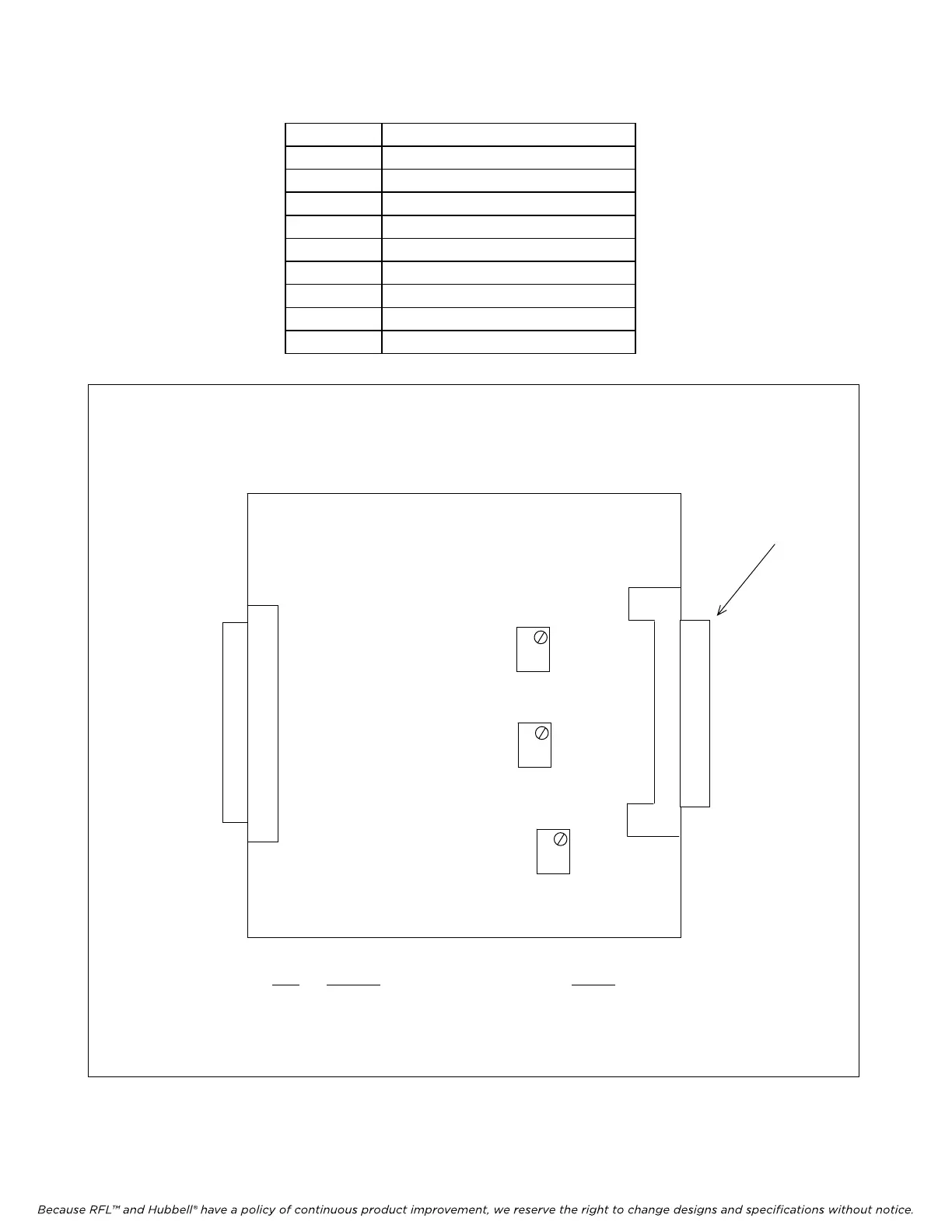
Item Function Setting
R2 Receive data output level adjust (factory adjustment)
R3 Transmit timing output level adjust (factory adjustment)
R4 Receive timing output level adjust (factory adjustment)
Connector J1
(See Table 3
R2
R3
R4
for pin assign-
ments)
Figure 3. Controls and indicators, MA-407I Module Adapter
RFL DS-562I RFL E
lectronics Inc.
June 14, 2007 10 (973) 334-3100