Because RFL™ and Hubbell® have a policy of continuous product improvement, we reserve the right to change designs and specifications without notice.
INSTALLATION AND OPERATION
The installation of the MA-428 is comprised of three parts: verification of switch settings, connecting
the MA-428 LAN Bridge to your LAN, and verification of LAN-to-LAN operation.
Verification of Switch Settings
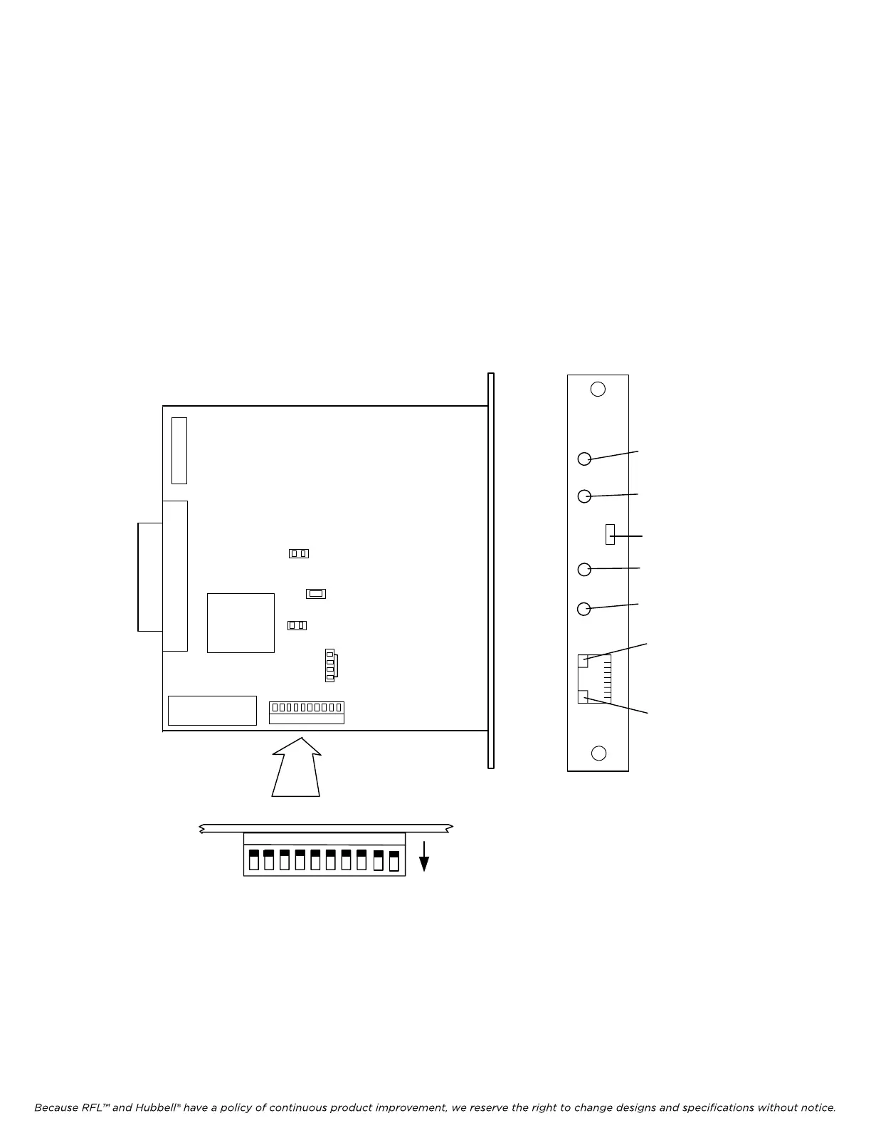
Verify that the MA-428 LAN Bridge’s switches are set to the defaults described in Table 23 on page
34. Refer to Figure 14 to locate the switches on the board. Following is an overview of the module
adapter’s controls and indicators:
SW2
MA-428
MA-428
Piano Switch Top View
UP
TX/RX
LINK
Link LED
L
A
N
LAN TX/RX
LED
Default positions
shown, see
Table 23
1
2
3
4
56
7
8
J6
J4
J1
HALF
10 MBPS
J5
910
ALARM
DROP
Reset Switch (SW1)
Alarm Light (D1)
Drop Light (D3)
10 Mbps Light (D2)
Half-duplex Light (D4)
JP2
JP1(ISP)
D7(TEST)
J2
Figure 14. MA-428 Enhanced LAN Bridge Module Adapter
RFL DS-562NC RFL Electronics Inc.
July 5, 2012 32 (973) 334-3100