Because RFL™ and Hubbell® have a policy of continuous product improvement, we reserve the right to change designs and specifications without notice.
RFL DS-562NC RFL Electronics Inc.
July 5, 2012 33 (973)
334-3100
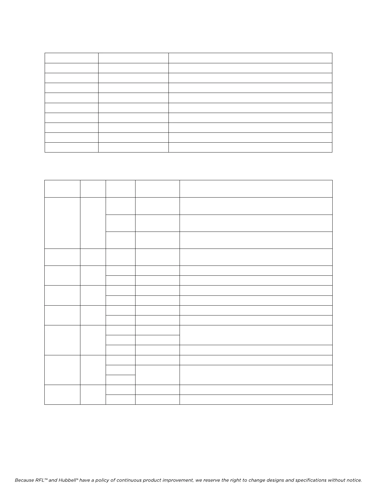
Table 21. MA-428 Controls and indicators
Switch/Jumper Function Description
SW1 Reset switch Allows for a manual reset in running condition
SW2 DIP switch bank Provides for various user-selectable inputs (See table 23)
J5 RJ-45 female For LAN side connection
J6 Back plane connector For backplane connection
J1 and J2 Jumpers Always leave open
D1 Alarm Indicator Front panel LED Indicator
D2 10/100 Mbps Indicator Front panel LED Indicator
D3 Drop indicator Front panel LED Indicator
D4 Half/full duplex mode Front panel LED Indicator
Table 22. MA-428 Indicator Light Description
Light
Indication
Color On/Off State Function
Blinks No valid link There may be a link between the module adapter and
the device, but it is not valid.
On Valid link There is a valid link between the module adapter and
the device.
LINK Green
Off No link There is no link between the module adapter and the
device.
TX/RX Yellow Blinks Frame
passing
Ethernet frames are passing.
On Half-duplex The module adapter is in half duplex mode.
HALF Green
Off Full-duplex The module adapter is in full duplex mode.
On 10Mbps The module adapter is operating at 10Mbps speed.
10MBPS Green
Off 100Mbps The module adapter is operating at 100Mbps speed.
Blinks Data lost Data is being lost. DROP
Yellow
Off No data lost No data is being lost.
Blinks Alarm 1
On Alarm 2
There is an alarm condition
ALARM
1
Red
Off Module OK There is no alarm condition.
Blinks Module OK The module adapter is functioning properly
On
TEST
2
Red
Off
Module not
OK
The module adapter is experiencing a problem
On Module on The module adapter is powered up.
POWER
2
Red
Off Module off There is no power to the module adapter.
1. The MA-428 module adapter’s ALARM indicator represents various alarm conditions, see Table 28.
2. These indicator lights are located on top of the board.