Because RFL™ and Hubbell® have a policy of continuous product improvement, we reserve the right to change designs and specifications without notice.
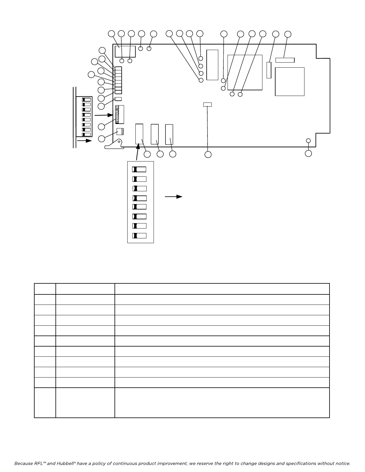
DIP Switch (typical)
2
1
3
4
5
6
7
8
ON - Right
1
2
3
4
5
6
8
7
End view of
Piano
Switches
UP
Right
1
2
3
4
5
6
7
8
9
10
11
12 13
14
15 16
17
18
19
20
21
22
23
24
25 26
30
31
27
28
29
SW2 SW3
SW4
SW1
J1
Figure 2. Controls and indicators, RFL OCUDP Selective Calling Unit
Table 1. Controls and indicators, RFL OCUDP Module
Item Name/Description Function
1 SVC LED, DS17 Lights green when card is in service
2 SPARE LED, DS8 Presently not used
3 SPARE LED, DS7 Presently not used
4 LN LB LED, DS6 Lights yellow when line loopback (local loopback) is active
5 CSU LB LED, DS5 Lights yellow when CSU (Channel Service Unit) loopback is active
6 OCU LB LED, DS4 Lights yellow when OCU (Office Channel Unit) loopback is active
7 ADIS LED, DS3 Presently not used
8 NOSX LED, DS2 Lights red when there is a sealing current
9 IDLE LED, DS1 Lights yellow when receiving idle code from customer loop
10 Piano Switch, SW1 SW1-1 Not used – Set to UP/RIGHT
SW1-2 Local/Remote (Local=UP/RIGHT, Remote=DOWN/LEFT)
SW1-3 to SW1-8 Sets SCB address (See Table 2)
RFL OCUDP RFL Electronics Inc.
July 15, 2010 6 (973) 334-3100