Because RFL™ and Hubbell® have a policy of continuous product improvement, we reserve the right to change designs and specifications without notice.
INSTALLATION
Before the RFL TMX Telemetry Transmitter module and the TMR Telemetry Receiver module can be
placed in service, they must be installed in their respective multiplexer shelves. Installation involves
determining the module slot in the Main Shelf or Expansion Shelf where the module will be installed,
inserting a Module Adapter into the rear of the shelf behind the module slot, connecting all signal
wiring to the Module Adapter, checking the settings of all switches and jumpers, and inserting the
module into the front of the respective shelf.
NOTES
Power supply and time slot considerations may affect the installation of this module into an
existing multiplexer shelf. Refer to the multiplexer manual for more information.
TMX Telemetry Transmitter Installation
The following instructions are provided for installing an RFL TMX Telemetry Transmitter module into
an existing system. If the module was included as part of a system, installation was done at the factory.
Otherwise, proceed as follows:
1. Carefully inspect the module for any visible signs of shipping damage. If you suspect damage
to the module, immediately call RFL Customer Service at the number listed at the bottom of
this page.
2. Determine the module slot in the Main Chassis or Expansion Chassis where the TMX module
will be installed. The RFL TMX Telemetry Transmitter module occupies one module slot in
the Main Shelf or Expansion Shelf.
3. Each module in the IMUX 2000 multiplexer requires a Module Adapter. The module adapter
provides the appropriate connector for the desired interface. The Module Adapter that is used
with the TMX is the MA-700 as shown in Figure 1.
4. On the MA-700 module adapter select a single ended or differential input for analog channels
1, 2, 3 and 4 using the programmable jumpers shown in Table 3, as applicable.
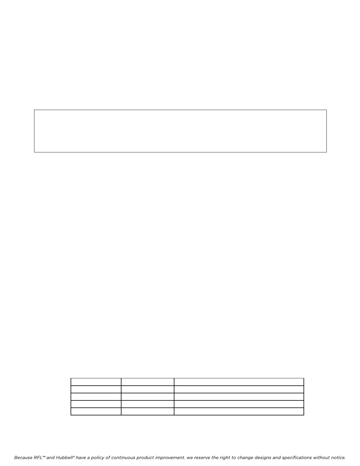
5. The information in this step is provided for users who wish to modify the input ranges of the
TMX through the use of external conversion resistors on the MA-700 module adapter. Table 1
describes what combinations of TMX inputs and TMR outputs require conversion resistors. If
conversion resistors are not required in your installation, go to step 6.
Table 1. Conversion resistor selection for each analog channel
TMX input TMR output Notes
Voltage input Current output Conversion resistors not required
Voltage input Voltage output Conversion resistors required at TMR only
Current input Voltage output Conversion resistors required at TMX and TMR
Current input Current output Conversion resistors required at TMX only
RFL TMX/TMR RFL Electronics Inc.
January 25, 2012 4 (973)
334-3100