Because RFL™ and Hubbell® have a policy of continuous product improvement, we reserve the right to change designs and specifications without notice.
RFL TMX/TMR RFL Electronics Inc.
January 25, 2012 5 (973)
334-3100
The RFL TMX module accepts voltage as an input and the RFL TMR module generates current
as an output. If you want to use current as an input instead of voltage, conversion resistor(s) are
required at the TMX. Place conversion resistor R1 across terminals TB2-1 and TB3-4 (for
analog channel 1), conversion resistor R2 across terminals TB2-2 and TB3-3 (for analog
channel 2), conversion resistor R3 across terminals TB2-3 and TB3-2 (for analog channel 3), or
conversion resistor R4 across terminals TB2-4 and TB3-1 (for analog channel 4), on the RFL
MA-700 module adapter (See Figure 2). The conversion resistors should have a precision of
0.01% to guarantee the system accuracy of +/-0.05%. Since the system accuracy applies to a
full-scale voltage input, the conversion resistor should be chosen so that the voltage across it is
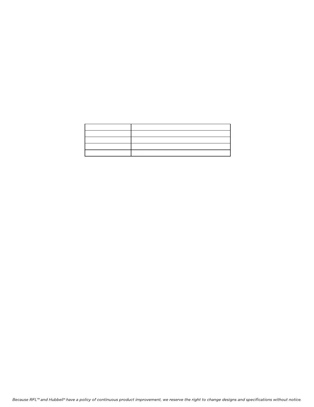
as high as practical and within one of the ranges shown in Table 2.
Table 2. Input gain versus input voltage range
Input Gain Input Voltage Range
1 -10V to +10V
2 -5V to +5V
4 -2.5V to +2.5V
8 -1.25V to +1.25V
For example, if an input current range of 0 to 50 mA is required, then a conversion resistor of
200 ohms will result in an equivalent voltage input of 0 to 10 volts at the A/D converter. The
resistor value is calculated as follows: 10V/50mA = 200 ohms, which is a readily available
value for a precision resistor.
6. After its jumpers are set and conversion resistors are installed if applicable, insert the MA-700
Module Adapter into the slot at the rear of the multiplexer chassis directly behind the module
slot where the RFL TMX module will be installed. Secure the module adapter with the screws
provided.
7. Connect the module adapter to the user equipment using the pin assignments listed in Figure 1
as applicable.
8. Refer to Figure 3 and Table 4 for the location and function of DIP switches on the TMX
module.
9. Set the SCB address using DIP switches SW1-1 through SW1-6 for the desired remote
address.
For remote access, each module in the IMUX 2000 must have a distinct module
address. Valid addresses are the numbers “1” to “36”. It is recommended to set the
address to the number of the slot the module is occupying. Table 6 shows the
switch settings for the module address. (Consult your multiplexer manual for
details on using the remote access and configuration features of the system.)
10. Select local or remote mode using SW2-7. UP places the module in remote mode (settings
obtained from the SCB), and DOWN places the module in local mode (settings obtained from
DIP switches). Set the switch to the DOWN position.