Because RFL™ and Hubbell® have a policy of continuous product improvement, we reserve the right to change designs and specifications without notice.
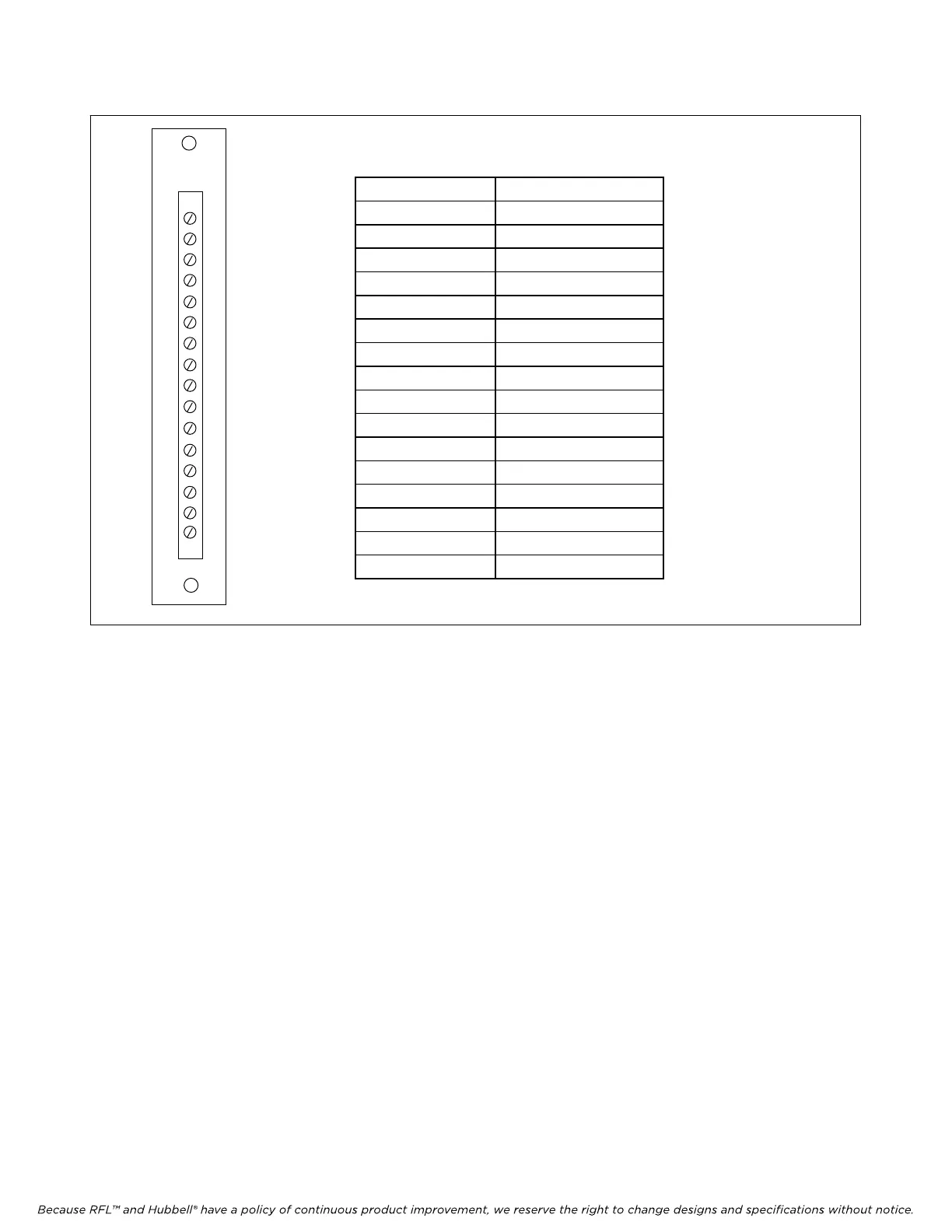
Terminal Number Function
1 Analog Channel 1+
2 Analog Channel 1-
3 Analog Channel 2+
4 Analog Channel 2+-
5 Analog Channel 3+
6 Analog Channel 3-
7 Analog Channel 4+
8 Analog Channel 4-
9 Calibration + Input
10 Calibration - Input
11 Not used
12 Alert Relay NO *
13 Not used
14 Alert Relay Common*
15 Not used
16 Alert Relay NC*
* ONLY USED ON
TMR MODULE
MA700
1
2
3
4
5
6
7
8
9
10
11
12
13
14
15
16
Figure 1. MA-700 Module Adapter for RFL TMX and TMR Telemetry modules
17. Select analog channel input gain using switches SW5-1 through SW5-8 as applicable. Input
gains of 1, 2, 4 or 8 can be selected for each analog channel in accordance with Table 4. Also
refer to Tables 11and 12 for recommended settings.
18. Input offset is always “0” when programming the TMX using DIP-switches.
19. Install the TMX module into the IMUX 2000 chassis and allow about 15 seconds for the board
to complete its power up process. This insures that the common module has read all
configuration data from the TMX module.
20. Proceed to install the TMR module in accordance with the instructions starting on page 15 of
this document. After the TMR module is installed verify TMX/TMR system operation by
performing the verification test at the end of this document. After performance has been
verified, set both modules to remote mode.
RFL TMX/
TMR RFL Electronics Inc.
January 25, 2012 7 (973)
334-3100