Because RFL™ and Hubbell® have a policy of continuous product improvement, we reserve the right to change designs and specifications without notice.
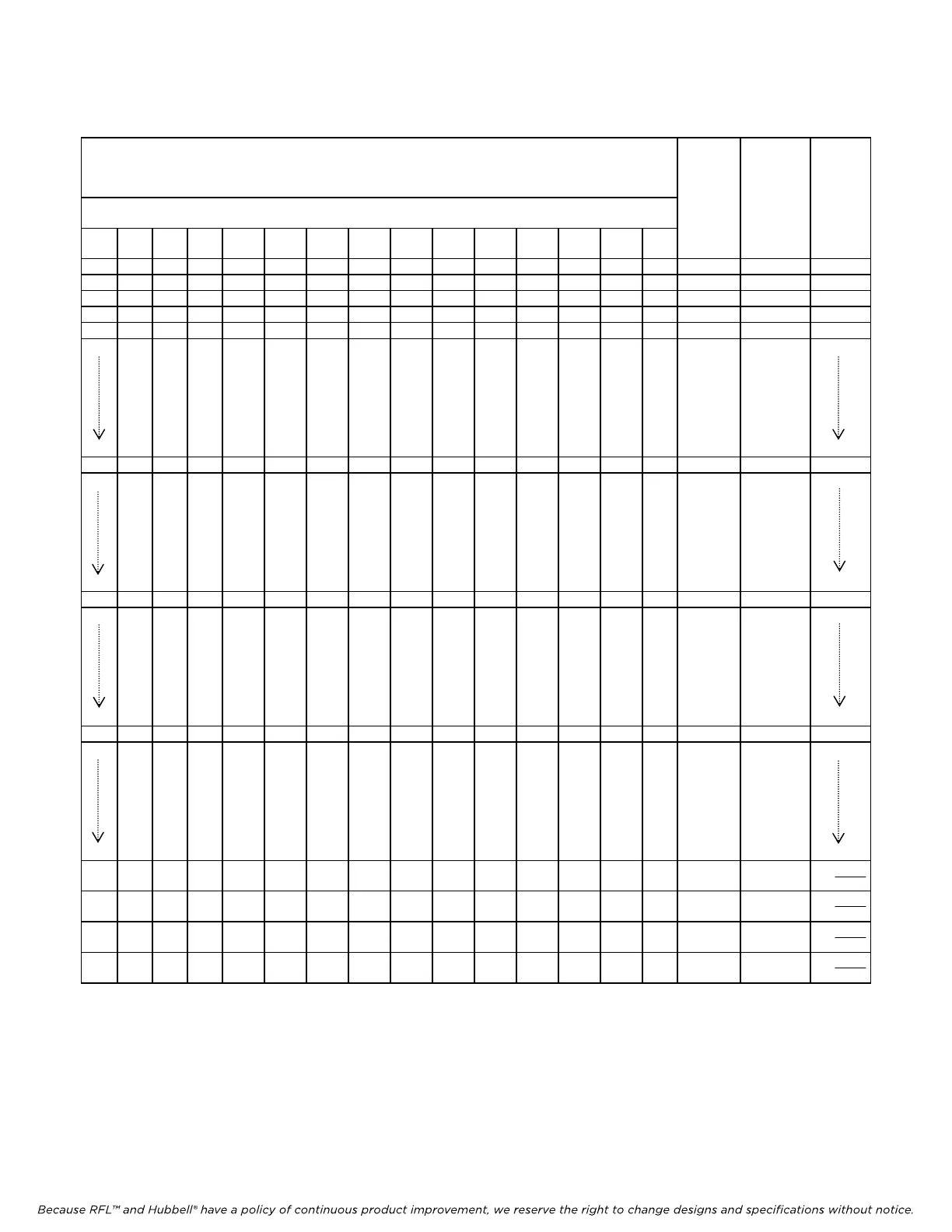
Table 20. Analog channel transfer ratio values
Transfer Ratio Setting in Binary
(1)
Decimal
Equiv-
alent
Multi-
plier
Trans-
fer
Ratio
Most Significant Byte Least Significant Byte
value
bit
6
bit
5
bit
4
bit
3
bit
2
bit
1
bit
0
bit
7
bit
6
bit
5
bit
4
bit
3
bit
2
bit
1
bit
0
0 0 0 0 0 0 0 0 0 0 0 0 0 0 0 0 x 1/2048 0
0 0 0 0 0 0 0 0 0 0 0 0 0 0 1 1 x 1/2048 1/2048
0 0 0 0 0 0 0 0 0 0 0 0 0 1 0 2 x 1/2048 2/2048
0 0 0 0 0 0 0 0 0 0 0 0 0 1 1 3 x 1/2048 3/2048
0 0 0 0 0 0 0 0 0 0 0 0 1 0 0 4 x 1/2048 4/2048
0 0 0 0 1 0 0 0 0 0 0 0 0 0 0 1024 x 1/2048 1/2
0 0 0 1 0 0 0 0 0 0 0 0 0 0 0 2048 x 1/2048 1
0 0 1 0 0 0 0 0 0 0 0 0 0 0 0 4096 x 1/2048 2
1 1 1 1 1 1 1 1 1 1 1 1 1 0 0 32,764
x 1/2048
1 1 1 1 1 1 1 1 1 1 1 1 1 0 1 32,765
x 1/2048
1 1 1 1 1 1 1 1 1 1 1 1 1 1 0 32,766
x 1/2048
1 1 1 1 1 1 1 1 1 1 1 1 1 1 1 32,767
x 1/2048
15
2044
2048
15
2045
2048
15
2046
2048
15
2047
2048
1.
The actual transfer ratio setting is a 15-bit value made up of a 7-bit section (MSB) and an 8-bit section (LSB).
2.
The transfer ratio setting represents the number of 1/2048 increments.
RFL TMX/TMR RFL Electronics Inc.
January 25, 2012 38 (973) 334-3100