Because RFL™ and Hubbell® have a policy of continuous product improvement, we reserve the right to change designs and specifications without notice.
IMUX 2000 VVS RFL Electronics Inc.
October 4, 2000 (973) 334-3100
2
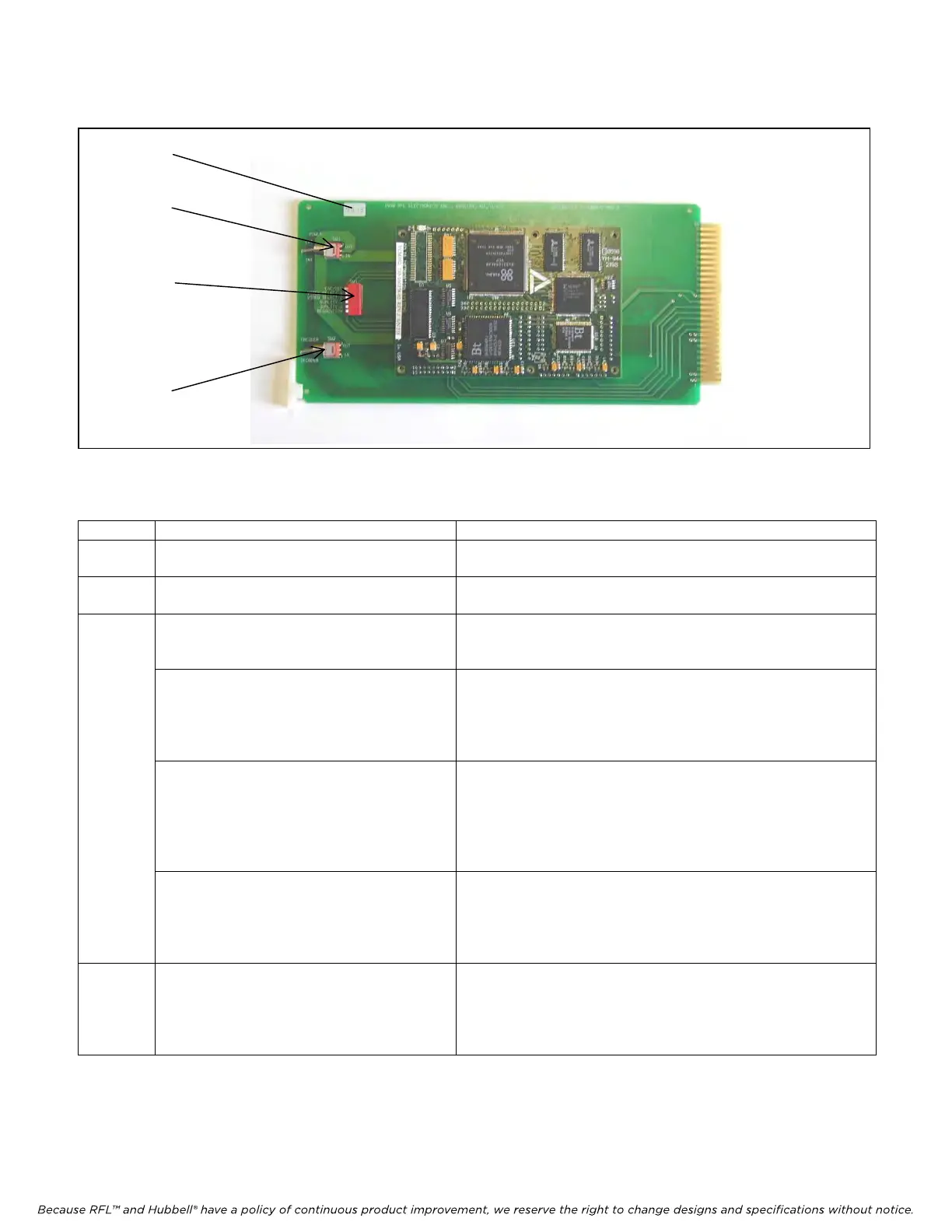
CONTROLS & INDICATORS
Figure 1. Location of controls and indicators on VS100 module
Table 1. Controls and indicators on the VS100
Item Name/Description Function
1 External Power SW1 Up configures unit for external +5V power
Down configures unit to use internal power
2 Encoder/Decoder SW2
Must be set before power is applied
Up configures unit as an encoder
Down configures unit as a decoder
3 Configuration SW3
ENC/DEC SW3-1
Must be set before power is applied
Position closest to PCB is closed
Closed configures unit as a decoder (must match SW2)
Configuration SW3
VIDEO SELECT 1 SW3-2
VIDEO SELECT 2 SW3-3
Set only on encoder, settings have no effect
on decoder unit.
Position closest to PCB is closed
Future use (must be open)
Future use (must be open)
Configuration SW3
QUALITY 1 SW3-4
QUALITY 2 SW3-5
Settings affect low speed operation only. Set
only on encoder, settings have no effect on
decoder unit.
Position closest to PCB is closed – see following table
IMAGE QUALITY SW3-4 SW3-5
BEST closed closed
BETTER
open closed
GOOD closed open
FAIR open open
Configuration SW3
RESOLUTION SW3-6
Settings affect low speed operation only. Set
only on encoder, settings have no effect on
decoder unit.
Position closest to PCB is closed
Closed = 176x144, Open = 352x288
4 Green LED “D6” There is only one indicator on the VS-100. The green LED
“D6” on the daughter board will illuminate steadily when the
module is working correctly. If the LED is off the module is
defective or is not receiving power. If the LED is blinking then
an error condition exists.
The controls and indicators on the DS64NC are described in the IMUX 2000 Operators Manual.
4
1
3
2