Because RFL™ and Hubbell® have a policy of continuous product improvement, we reserve the right to change designs and specifications without notice.
Mode Description
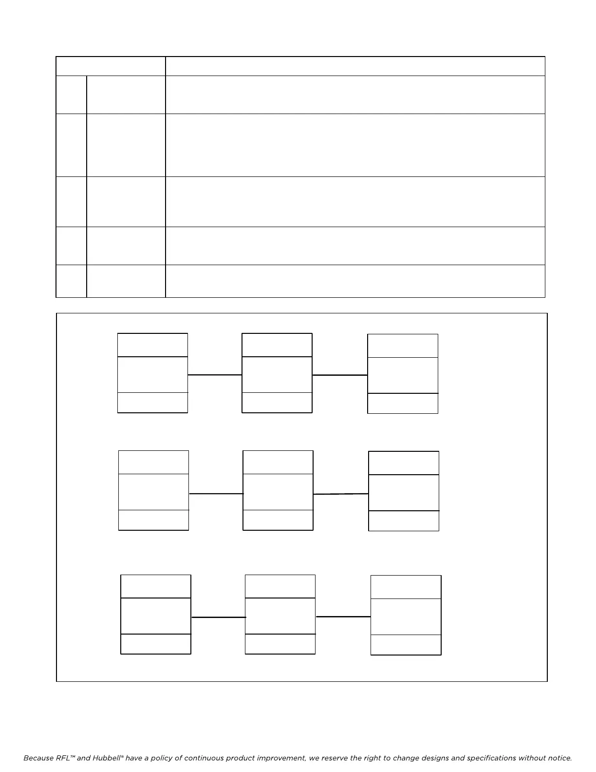
1 Broadcast In Broadcast mode each node transmits to and receives from all other nodes in the
network. Typically when Broadcast mode is used, all nodes in the network are set to
Broadcast mode. Refer to Figure 13a for more information.
2 NMS Typically when NMS mode is used, all nodes in the network are set to NMS mode. In
NMS mode each node transmits to all other nodes and each node selectively receives
messages from all other nodes in the network based upon addressing. In addition to
this, each node transmits its address to adjacent nodes during idle network time. Refer
to Figure 13b for more information.
3 Master Typically, when one of the nodes in a network is a master, the other nodes are slave
nodes. There are two types of slave nodes: D&I slave nodes and End slave nodes.
Refer to Figure 13c for a typical network using Master and Slave nodes. The Master
node transmits to all other nodes in the network.
4 D&I Slave The D&I slave node only receives from and transmits to the master node, and it also
allows messages from the master to pass through to all other slaves. It also allows
messages from other slaves to pass through to the master.
5 End Slave The End slave node only receives messages from and transmits messages to the
master node
IMUX 2000
IMUX 2000
IMUX 2000
IMUX 2000
IMUX 2000
IMUX 2000
IMUX 2000
IMUX 2000
IMUX 2000
MA-485 MA-485
MA-485
MA-490 MA-490 MA-490
MA-4021 MA-4021 MA-4021
NCM in
Broadcast
mode
NCM in
Broadcast
mode
NCM in
Broadcast
mode
NCM in NMS
mode
NCM in NMS
mode
NCM in NMS
mode
NCM in Master
mode
NCM in D&I
Slave mode
NCM in End
Slave mode
Figure 13a Typical 3-node network using MA-485s (1 RS-485 port)
Figure 13b Typical 3-node network using MA-490s (1 RS-232 port, 1 Ethernet port)
Figure 13c Typical 3-node network using MA-4021s (2 RS-232 ports)
Node 1
Node 2
Node 3
Node 1
Node 1
Node 2
Node 2
Node 3
Node 3
Figure 13. Typical networks showing NCM module configured as Master, D&I Slave, End Slave, Broadcast and N
RFL NCM RFL Electronics Inc.
November 1, 2012 36 (973)
334-3100