Because RFL™ and Hubbell® have a policy of continuous product improvement, we reserve the right to change designs and specifications without notice.
2. Rogue Detection
Rogue Detection can be enabled or disabled, and can be used in any mode but is typically used in
NMS mode. When enabled it monitors the local ports and the receive T1 messages. Rogue Detection is
used to prevent a rogue PC program or another module from “stepping on” the NCM time slot and
bringing down the entire NCM path. If enabled, both the local input(s) and T1 receive inputs will
monitor for rogue activity. The local input port is squelched for at least 2 minutes once a continuous
data stream lasting for greater than 60 seconds is detected. The T1 receive data is squelched for 2
minutes once a continuous data stream greater than 64 seconds is detected on the bus. The T1 rogue
threshold is set intentionally higher than the local port to prevent all the nodes from reacting to a rogue
at any of the local ports.
CM ADDRESS
3. CM Address Pass
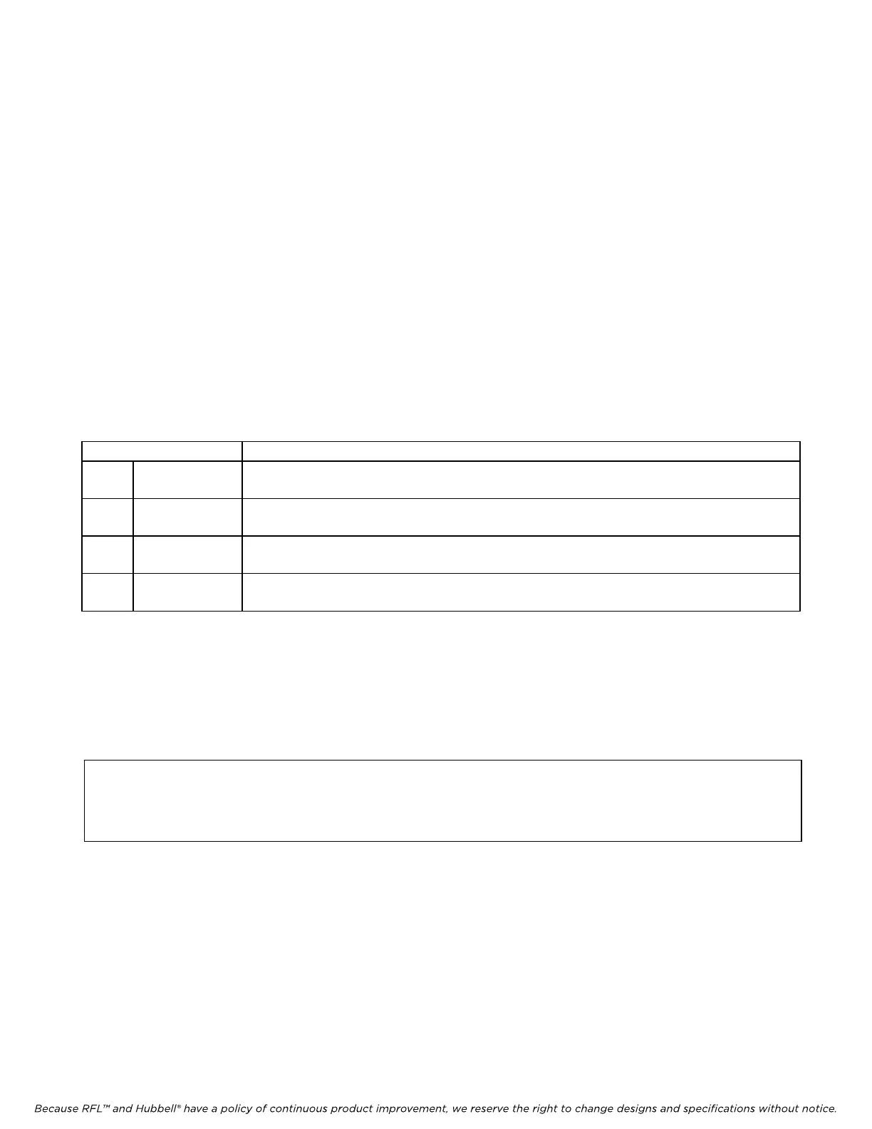
The CM Address Pass setting controls the range of addressed messages that are allowed to pass from
the NCM to the local common module in accordance with the table below. There are four CM Address
Passing settings as follows, Any, = =, > =, and < = .
CM Address Pass Description
1 Any Will pass any messages regardless of the “Local CM Address” setting of the NCM.
Messages without address headers are also passed.
2 = = Will only pass messages with addresses equal to the “Local CM Address” setting of
the NCM
3 > = Will only pass messages with addresses greater than or equal to the “Local CM
Address” setting of the NCM
4 < = Will only pass messages with addresses less than or equal to the “Local CM Address”
setting of the NCM
4. Local CM Address
The “Local CM Address” for the NCM module must be set to the same address as the local Common
Module (CM3B, CM3C, CM3R, CM6B, or CM4). The NCM supports addresses from 1 to 999 (see
note below) and is set by using the up and down arrows in the hundreds, tens and units boxes as shown
in Figure 14. For example, if your CM4 is set to Address 351, the “CM Address” of the NCM must be
set to 351.
NOTE
The CM3B, CM3C and CM6B support addresses from 1 to 99. The CM4 and CM6B support
addresses from 1 to 500.
After all settings are made on the Mode page (Figure 13), click on the Port tab to get to the Port
window as shown in Figure 14.
RFL NCM RFL Electronics Inc.
November 1, 2012 37 (973)
334-3100