• To avoid breaking the tabs under the left edge of the table, pull the table to the right to disengage
the tabs and then remove.
5. Inverter exit sensor [E] ( x 1, harness x 1, x 1)
6. Transport sensor 1 [F] (harness x 1, x 1)
7. Transport sensor 2 [G] (harness x 1, x 1)
Duplex Jogger Belt Adjustment
Remove:
• Cross stay. See "Inverter Exit Sensor, Transport Sensors 1 & 2"
• Reverse trigger roller shaft. See "Inverter Exit Sensor, Transport Sensors 1 & 2"
• Left half of the table
• Jogger motor bracket
• Slip the one end of the belt around the gear below the jogger motor.
• Slip the other end of the belt around the gear at the other side of the duplex unit.
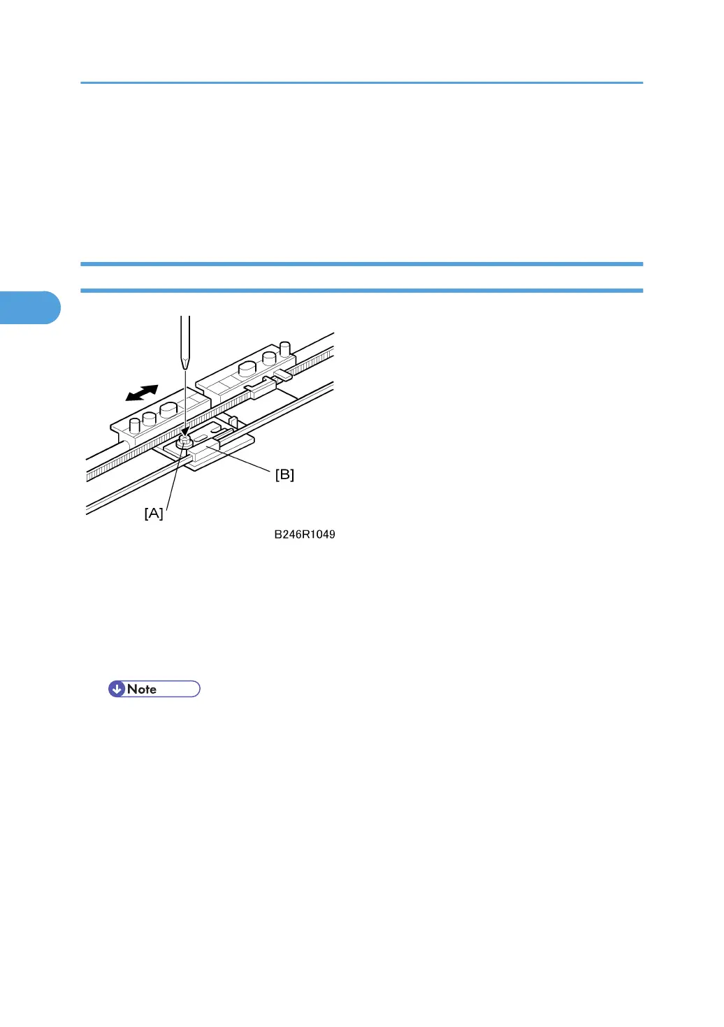
1. If you are replacing the belt, set both jogger fence brackets at the center of the belt and
tighten the screw [A].
2. If you are adjusting the belt, loosen the screw and slide the plastic piece [B] on the belt to
the left or right to adjust the position of the front fence, then tighten the screw.
3. Replacement and Adjustment
204