2. For every copy, Vt (TD sensor output) is subtracted from Vref (the targeted control reference voltage
for the TD sensor) to set the value of ‘GAIN’ (0, 1, 2, 3, or 4).
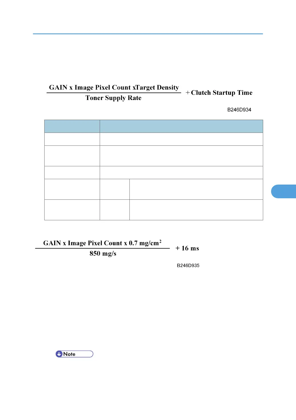
3. The following equation is used to calculate how long the toner supply clutch switches on.
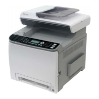
Factor Description
GAIN With GAIN = 0, “Clutch On Time” is 0 ms
Image Pixel Count
The density for every dot in the output data for the page is calculated.
Example: 255 for A3 all black, for comparison.
Target Density 0.7 mg/cm2
Toner Supply Rate 850 mg/s
This default setting can be adjusted with SP2209 – Toner
Supply Rate
Clutch Startup Time 16 ms
The actual time required for the toner to arrive at the hopper
after the clutch switches on.
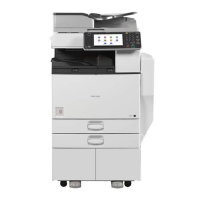
If we substitute the default settings, then:
But if GAIN is 0, the ‘+16 ms’ part of the equation is not used, and the time interval that the clutch is turned
on becomes zero.
At the end of the job, if Vref has not been updated for 10 copies or more, the following occurs:
1. Vref is updated, as follows (also done just after the machine is switched on):
• The charge corona and laser diode write the ID sensor pattern on the drum.
• The ID sensor reads the reflectivity of the ID sensor pattern and outputs this reading as Vsp.
• The ID sensor also reads the reflectivity of the bare surface of the drum and outputs this reading
as Vsg.
• The 10 copy interval can be extended with SP2210-001 (ID Sensor Pattern Interval).
Development and Toner Supply
469