DISPLAY PANEL MANUAL
16-9
16.3.3 I/O Memory
I/O memory are exclusive memory area between ARCNET communication unit and Touch Panel.
I/O memory has 7 block of I/O1 to I/O7. Each block consists of 256 words. Refer to followings for general
contents of each block.
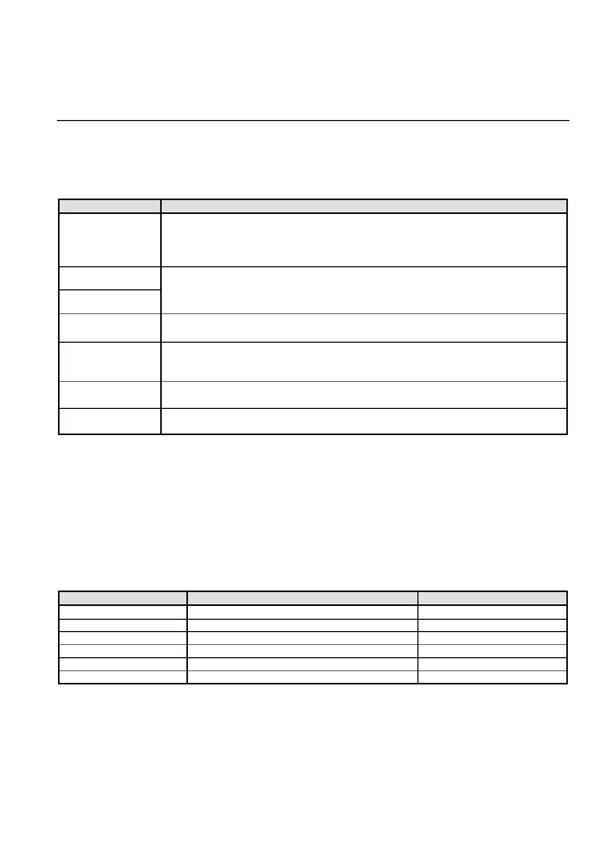
I/O memory CONTENTS
I/O memory 1
・ Control memory for overlap or comment
・ Control memory for Read / Write Area
・ Flags
・ Others
I/O memory 2
I/O memory 3
Buffer memory area for Fastening Setting mode
I/O memory 4 Buffer memory area for Data Display mode
I/O memory 5
・ Buffer memory area for attribute change at each mode (Data format, Digits,
Decimal point, etc.)
・ Auxiliary data for indicating in Data Display mode
I/O memory 6
・ Display data in Maintenance mode
・ Display data in Torque Curve Display mode
I/O memory 7
Receive data, Receive data set status, Connecting status, Receive data mode
status, Current screen No., NR mode screen No., etc.
Figure 16.3-5 I/O memory
Do not write to I/O memory in principle because it might cause influence operation of the NUTRUNNER.
Exceptionally, Read Area of I/O memory 1 can be written. However, it is necessary to write indirectly by
using Device Memory Map, Macro and etc.
Receive data and receive status from NUTRUNNER can be get by reading I/O memory 7. Refer to next
page for detail.
Refer to ’Chapter 17 NR Data Receive Function’ for detail about this function.
● I/O memory 1
Address CONTENTS Data Format
080 Read Area 1 Binary
081 Read Area 2 Binary
082 Read Area 3 Binary
083 Write Area 1 Binary
084 Write Area 2 Binary
085 Write Area 3 Binary
Figure 16.3-6 I/O1 Read / Write Area