9. TORQUE CURVE DISPLAY mode
9-6
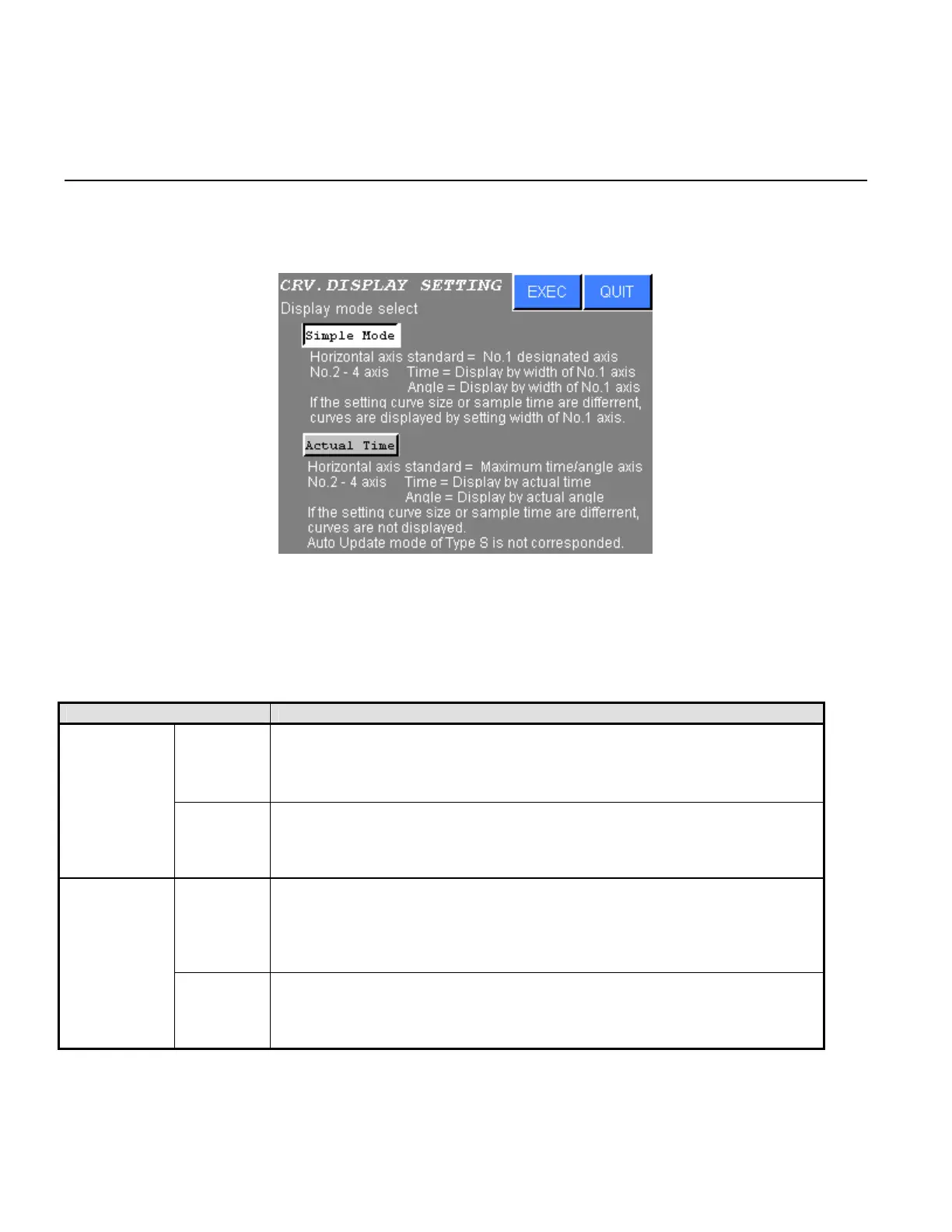
9.1.2 DISPLAY SETTING
1) The following screen will be displayed when the DISPLAY SETTING is selected from the CURVE
DISPLAY MODE.
Figure 9.1-4 CURVE DISPLAY setting
2) Press touch switch of the desired setting.
Press EXEC to write new settings.
Press QUIT to cancel all edits and return to the CURVE DISPLAY MODE.
DISPLAY MODE CONTENTS
Time
Horizontal axis standard is No.1 designated axis. Display NR No.2 to 4
are displayed by range of Display NR No.1. They are not actual time. If
settings of their “Trq.Crv.Samp.Int” “Trq.Crv.Dt.size” are different, actual
time range of them are different.
Simple Mode
Angle
Angle range of horizontal axis is adjusted by tightening angle of Display
NR No.1.
All NR are displayed by actual angle. If No.2 to 4 angle data is larger than
No.1 angle data, No.2 to 4 angle data might not display in the screen.
Time
Sampling time of the torque curve is designated by “Trq.Crv.Samp.Int”
“Trq.Crv.Dt.size” control parameter of maximum cycle time NR.
All NR are displayed by actual time. If settings of their “Trq.Crv.Samp.Int”
“Trq.Crv.Dt.size” are different, their torque curve are not displayed.
AUTO UPDATE of Type S is not corresponded.
Actual Time
Angle
Angle range of horizontal axis is adjusted by maximum tightening angle of
DISPLAY NR No.1 to 4.
ALL NR are displayed by actual angle.
AUTO UPDATE of Type S is not corresponded.
Table 9.1-2 DISPLAY MODE SETTING
.