U.4.60
SEL-421 Relay User’s Guide Date Code 20090715
Basic Relay Operations
Operating the Relay Inputs and Outputs
Controlling a Relay Control Output With a Local Bit: Terminal
In this example, you set Local Bit 3 to start the transformer cooling fans near
the breaker bay where you have installed the SEL-421. Thus, you can use the
LCD screen and navigation pushbuttons to toggle relay Local Bit 3 to control
the state of the cooling fans. Relay Word bit LB_SP03 provides supervision
for local bit 3. Relay Word bit LB_SP03 must be asserted for successful Local
Bit 3 operations. For more information on local bits, see LOCAL CONTROL
BITS on page U.5.24.
The procedure in the following steps proposes connecting the transformer
bank fan control to relay output OUT105. You can choose any relay output that
conforms to your requirements. See Control Outputs on page U.2.7 for more
information on SEL-421 control outputs.
This example assumes that you have successfully established communication
with the relay (see Making an EIA-232 Serial Port Connection on page U.4.5).
In addition, you must be familiar with relay access levels and passwords (see
Changing the Default Passwords: Terminal on page U.4.9 to change the
default access level passwords).
Step 1. Prepare to control the relay at Access Level 2.
a. Using a communications terminal, type ACC <Enter>.
b. Type the Access Level 1 password and press <Enter>.
You will see the Access Level 1 => prompt.
c. Type the 2AC <Enter> command.
d. Type the correct password to go to Access Level 2.
You will see the Access Level 1 =>> prompt.
Step 2. Access the local control settings.
a. Type SET F <Enter> command.
b. Repeatedly type > and then <Enter> to advance
through the front-panel settings until you reach the
Display Points and Aliases category.
c. Press <Enter> to access the Control Points and
Aliases Category.
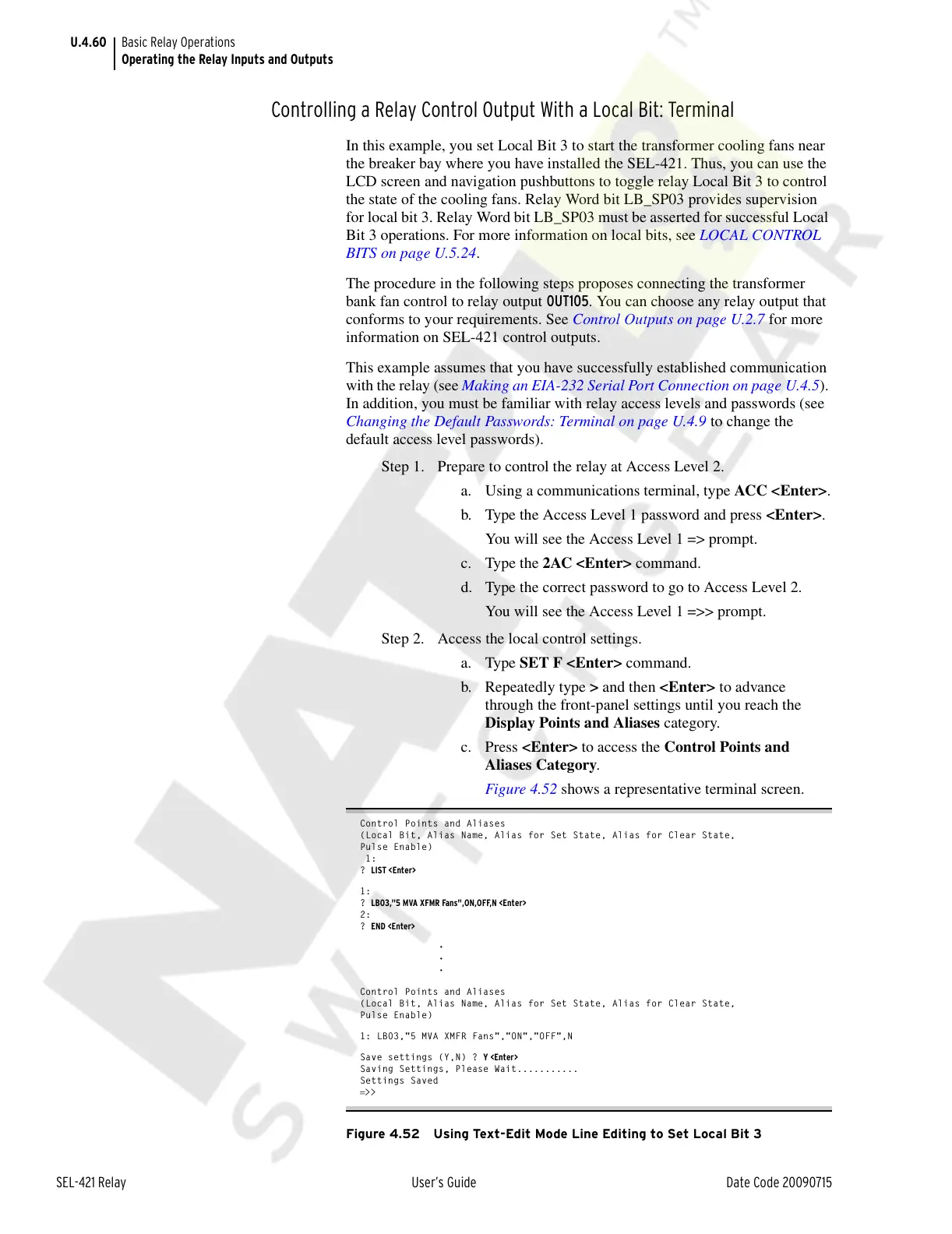
Figure 4.52 shows a representative terminal screen.
Control Points and Aliases
(Local Bit, Alias Name, Alias for Set State, Alias for Clear State,
Pulse Enable)
1:
? LIST <Enter>
1:
? LB03,"5 MVA XFMR Fans",ON,OFF,N <Enter>
2:
? END <Enter>
•
•
•
Control Points and Aliases
(Local Bit, Alias Name, Alias for Set State, Alias for Clear State,
Pulse Enable)
1: LB03,"5 MVA XMFR Fans","ON","OFF",N
Save settings (Y,N) ? Y <Enter>
Saving Settings, Please Wait...........
Settings Saved
=>>
Figure 4.52 Using Text-Edit Mode Line Editing to Set Local Bit 3
Courtesy of NationalSwitchgear.com