Adapting the terminal strip
6.5 Analog outputs
Inverter with CU230P-2 Control Units
Operating Instructions, 11/2013, FW V4.6.6, A5E02430659B AG
105
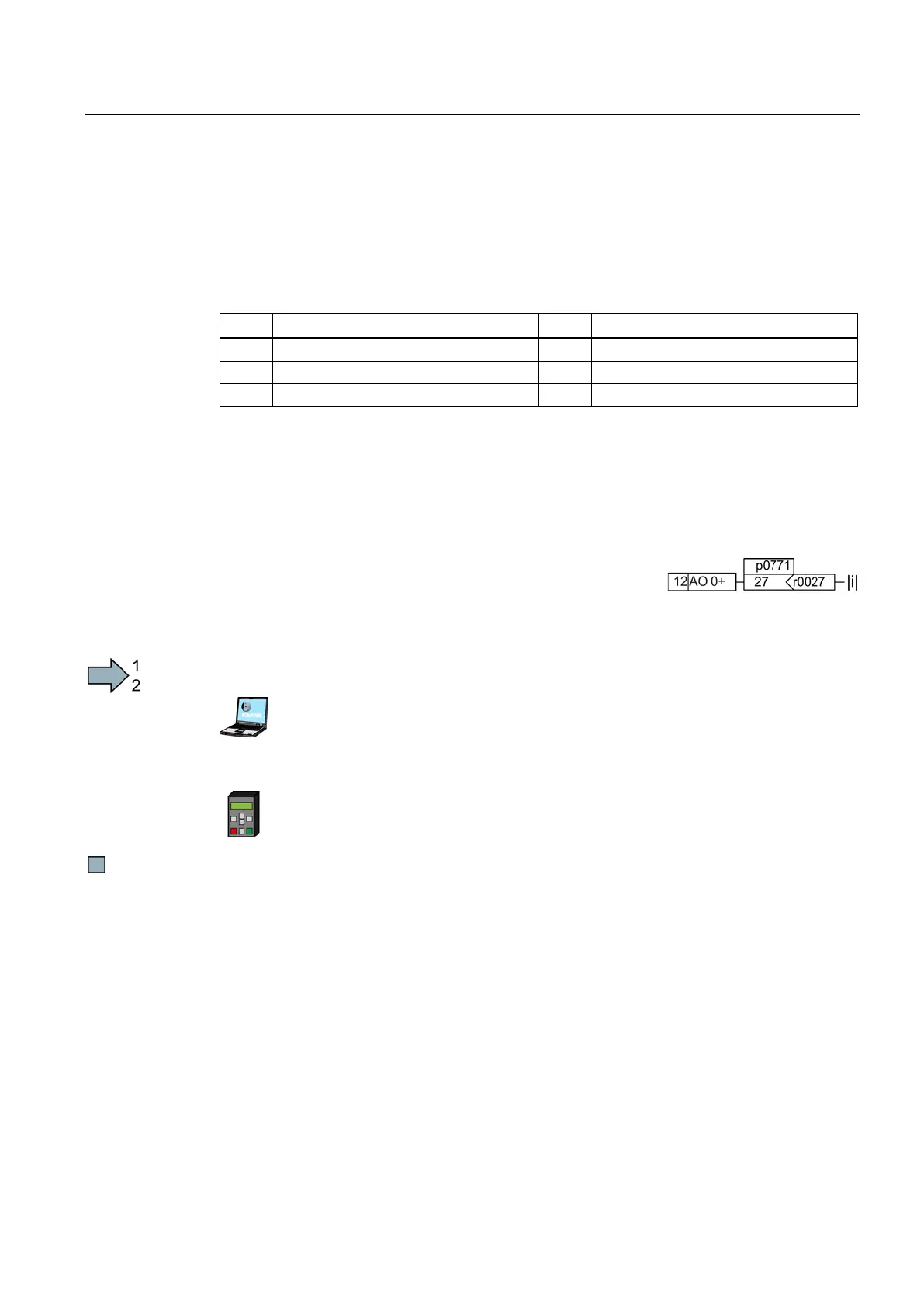
Internal interconnection of the analog output
You define the analog output function by interconnecting parameter p0771 with a connector
output of your choice. Parameter p0771 is assigned to the particular analog input via its
index, e.g. parameter p0771[0] is assigned to analog output 0.
Table 6- 5 Connector outputs (CO) of the inverter (selection)
A complete list of the connector outputs is provided in the List Manual.
For more information, please see the parameter list and the function block diagrams 9572 f
of the List Manual.
Adapting the internal interconnection of the analog output - Example
You wish to output the inverter output current via analog
output
0. To do this, you must connect AO 0 with the signal
Proceed as follows to interconnect analog output 0 with the signal for the output current:
Go online.
Select "Inputs/outputs".
Change the output function via the corresponding screen form.
Go into the menu "PARAMS".
As a parameter filter, select "EXPERT".
Set p0771 = 27
You have interconnected analog output 0 with the signal for the output current.
You can manipulate the signal that you output via an analog output, as follows:
● Absolute-value generation of the signal (p0775)
● Signal inversion (p0782)
Additional information is provided in the parameter list of the List Manual.

 Loading...


