4 Operation
Attachments
6219_003-052_V3
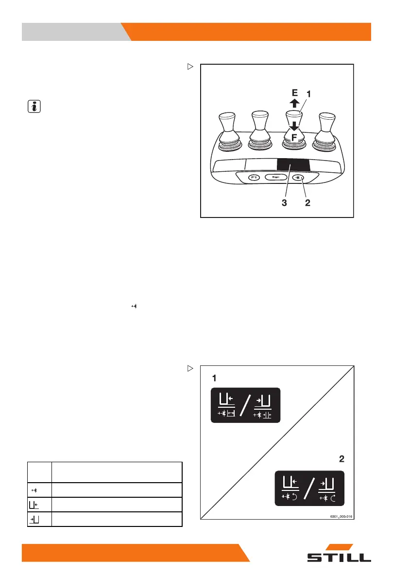
Controlling attachments usi
ng
the quadruple mini-lever an
dthe
5th function
NOTE
For technical reasons, clamping attachments
must not be controlled via the "5th function".
The function key for the "5th function" (2) and
the operating lever (1) are used to control the
"5th function".
The adhesive label bearing the pictograms
for the hydraulic functions (3) is affixed at the
designated point.
– If the adhesive label becomes illegible or
is missing, please contact your authorised
service centre.
– Observe the pictograms for the attachment
functions on the adhesive label (3).
This essentially involves the following:
– Actuate the function key for the "5th func-
tion" (2).
The LED for the "5th function"
lights up.
– Move the operating lever (1) in the direc-
tion (E) or (F).
The attachment moves accordingly in the
directions (E) or (F) as shown in the pictogram.
Example using the pictograms for configura-
tion (1):
If the operating lever (1) is moved in the
direction of the arrow (E), the sideshift moves
to the left.
If the function key for the "5th function" (2) is
actuated and the operating lever (1) is moved
in the direction of the arrow (E), the fork arms
open.
Picto-
gram
Attachment function
Auxiliary hydraulics "5th function"
Move the sideshift to the left
Move sideshift to the right
244
56368011531 EN - 06/2019 - 02