Operation 4
Attachments
2
6219_003-047_V2
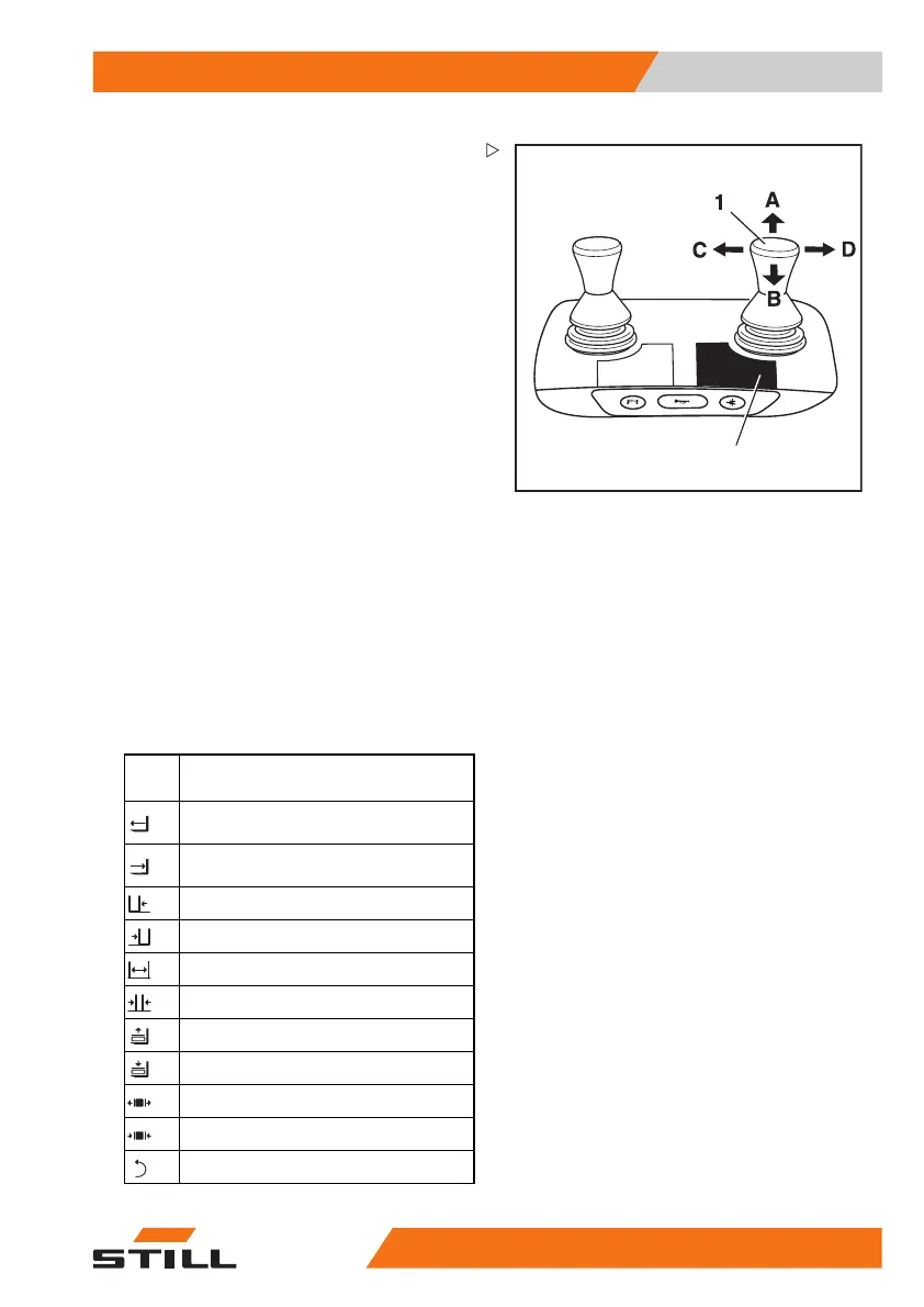
Controlling attachments usi
ng a
double mini-lever
In this version, the attachm
ents (variant) are
controlled using the "attac
hments" cross
lever (1). The adhesive labe
l bearing the
pictograms for the hydrauli
c functions (2) is
affixed at the designated po
int.
– If the adhesive label becomes illegible or
is missing, please contact your authorised
service centre.
– Observe the pictograms for the attachment
functions on the adhesive label (2).
The pictograms on the "at
tachments" cross
lever (1) show the respec
tive functions that
are activated by this lev
er.
The pictograms are arranged according to
the direction of movement of the "attach-
ments" cross lever (1).
The following applies:
– Move the "attachments
" cross lever(1) in
the direction of arrow
(A), (B), (C) or (D).
The attachment moves accordingly in the
directions (A), (B), (C) or (D) as shown in the
pictogram.
Picto-
gram
Attachment function
Move the side shift frame or fork
forwards
Move the side shift frame or fork
backwards
Move the sideshift to the left
Move sideshift t
otheright
Adjust fork arm
s: open
Adjust fork ar
ms: close
Release load retainer
Clamp load retainer
Open clamps
Close clamps
Rotate to the left
563
68011531 EN - 06/2019 - 02 235