Operation 4
Attachments
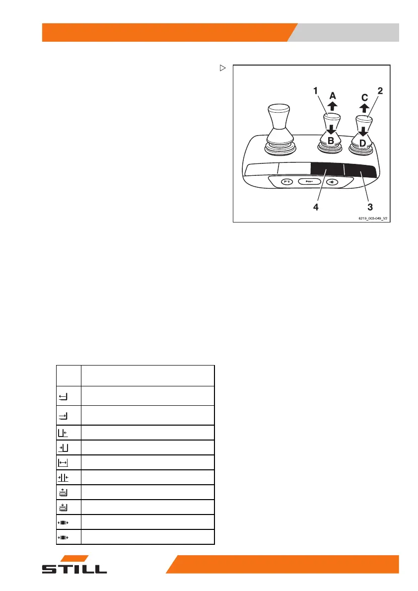
Controlling attachments usi
ng a
triple mini-lever
In this version, the attachm
ents (variant) are
controlled using the operat
ing levers (1, 2).
The adhesive label bearing t
he pictograms for
the hydraulic functions (3)
for the operating
lever (2) and the adhesive l
abel (4) for the op-
erating lever (1) are affixe
d at the designated
points.
– If the adhesive labels become illegible or
are missing, please contact your authorised
service centre.
– Observe the pictograms for the attachment
functions on the adhesive labels (3, 4).
The pictograms on the ope
rating levers show
the respective function
s that are activated by
these levers.
The following applies:
– Move the operating lever (1) in the direction
of the arrow (A) or (B).
The attachment moves a
ccordingly in the
directions (A) or (B) a
s shown in the pictogram.
– Move the operating lever (2) in the direction
of the arrow (C) or (D).
The attachment moves accordingly in the di-
rections (C) or (D) as shown in the pictogram.
Picto-
gram
Attachment functio
n
Move the side shift frame or fork
forwards
Move the side shift frame or fork
backwards
Move the sideshift to the left
Move sideshift to the right
Adjust fork arms: open
Adjust fork arms: close
Release load retainer
Clamp load
retainer
Open clamp
s
Close cla
mps
563
68011531 EN - 06/2019 - 02 239