Power plug connector features
Motor type Size Connection Turning range
α β
EZ2, EZ3 con.15 Quick lock 180° 140°
EZ4, EZ5, EZ701, EZ702, EZ703 con.23 Quick lock 180° 40°
EZ705, EZ802, EZ803, EZ805 con.40 Quick lock 180° 40°
Encoder plug connector features
Motor type Size Connection Turning range
α β
EZ2, EZ3 con.15 Quick lock 180° 140°
EZ4, EZ5, EZ7, EZ802, EZ803, EZ805 con.17 Quick lock 195° 35°
Notes
• The number after "con." indicates the approximate external thread diameter of the plug connector in
mm (for example, con.23 designates a plug connector with an external thread diameter of about 23
mm).
• In turning range β, the power or encoder plug connectors can be turned only if doing so does not cause
them to collide.
• For the EZ3 motor, the power and encoder plug connectors are mechanically connected and can only
be turned together.
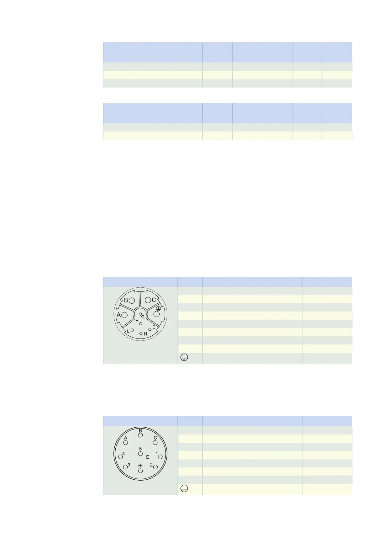
11.6.8.4 Terminal assignment for plug connectors (One Cable Solution)
In the One Cable Solution design, the power and encoder lines are connected using a shared plug connector.
The temperature sensor of the motor is connected to the encoder internally. The measured values from the
temperature sensor are transmitted via the EnDat 3 protocol of the encoder.
Plug connector size con.23
Connection diagram Pin Connection Color
A U phase BK
B V phase BU
C W phase RD
E P_SD – YE
F
G Brake +
H P_SD + VT
L Brake −
Grounding conductor GNYE
11.6.8.5 Connection assignment of the power plug connector
The size and connection plan of the power plug connector depend on the size of the motor. The colors of
the connecting wires inside the motor are specified in accordance with IEC 60757.
Plug connector size con.15
Connection diagram Pin Connection Color
A U phase BK
B V phase BU
C W phase RD
1 Temperature sensor +
2 Temperature sensor −
3 Brake + RD
4 Brake − BK
Grounding conductor GNYE
11 EZsynchronous servo motors 11.6 Product description
407