Functional Parameter Table
V560 Series High Performance Closed-Loop Vector Inverter User Manual
96
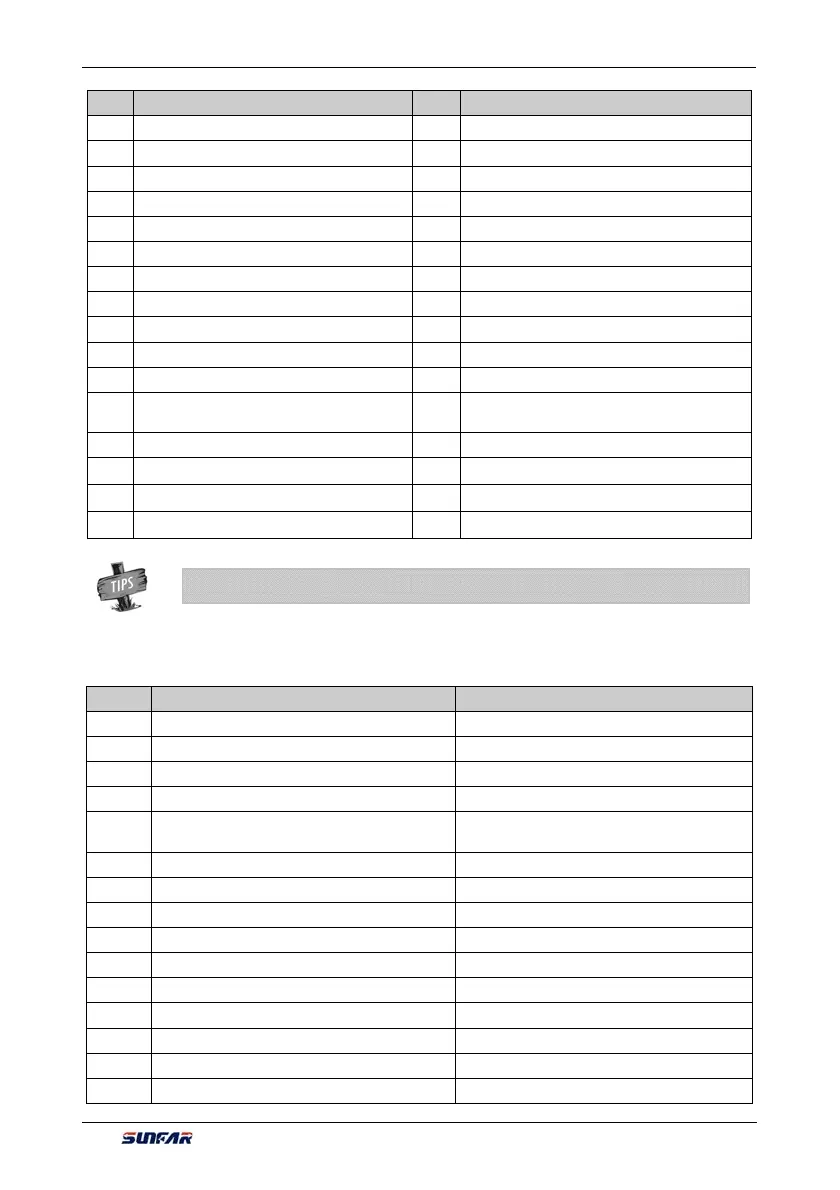
S/N Function S/N Function
40 Counter 1 output signal 1 41 Counter 1 output signal 2
42 Counter 2 output model 1 43 Counter 2 output signal 2
44 Timer 1 output signal 1 45 Timer 1 output signal 2
46 Timer 2 output signal 1 47 Timer 2 output signal 2
48 Timer 3 output signal 1 49 Timer 3 output signal 2
50 Extension modules retained 51 Extension modules retained
52 Extension modules retained 53 Extension modules retained
54 Extension modules retained 55 DI1 terminal status effective
56 DI2 terminal status effective 57 DI3 terminal status effective
58 DI4 terminal status effective 59 DI5 terminal status effective
60 DI6 terminal status effective 61 DI7 terminal status effective
62 DI8 terminal status effective 63
Terminal as frequency output (only applicable to
DO3/FO terminal)
64 SDO1 LDI 65 SDO2 LDI
66
SDO1⊙SDO2 AND
67
SDO3⊙SDO4 AND
68
SDO5⊙SDO6 AND
69
SDO3⊕SDO4 OR
70
SDO5⊕SDO6 OR
71
SDO7⊕SDO8 OR
Table 3: Comparison Table of Monitor Variables
S/N Monitoring Parameter Variable 100% full-scale output
0 Output frequency (rotor synchronous frequency) Upper limiting frequency
1 Motor Revolution Upper limiting frequency*60/pairs of motor poles
2 Output current 250%*Inverter rated current
3 Output torque 300% rated torque
4 Output voltage
Motor rated voltage (reference voltage in V/F
mode)
5 Output power 2* motor rated power
6 Maximum temperature of the equipment 150.0°C
7 Voltage at the DC side 1000V (single phase 500V)
8 Motor temperature/ PTC resistance 500.0°C / 5000Ω
9 Frequency setting channel set value Upper limiting frequency
10 Speed command Upper limiting frequency*60/pairs of motor poles
11 Torque command 300% rated torque
12 Target operating frequency Upper limiting frequency
13 Reserved ——
14 Speed adjuster deviation Upper limiting frequency*60/pairs of motor poles
¾ Direction will not be considered for comparison of monitor variables
 Loading...
