Description Of Specific Functions 145
V560 Series High Performance Closed-Loop Vector Inverter User Manual
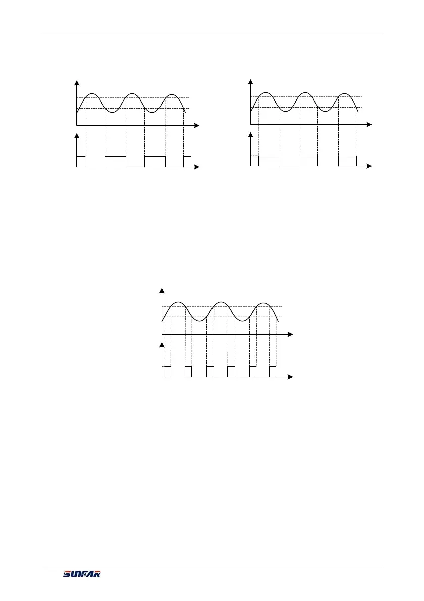
When monitoring parameters 1/2/3 are below the lower limit values, terminal will output the valid signal/relay
will pull in, which keeps until monitoring parameters 1/2/3 are above the upper limit values, then output the
invalid signal/relay disconnects (as shown in Figure 7-34-A).
27/30/33: Monitoring parameters 1/2/3 above the lower limit
When monitoring parameters 1/2/3 are above the upper limit values, terminal will output effective signal/relay
will pull in, which keeps until monitoring parameters 1/2/3 are below the lower limit values, then output
ineffective signal/relay disconnects (as shown in Figure 7-34-A)
28/31/34: Monitoring parameters 1/2/3 between the upper limit and the lower limit
When monitoring parameters 1/2/3 are between upper and lower limit values (including equal to upper and
lower limit values), the terminal will output the indicator signal/relay will pull in.
36~38: Analog input AI1 wire-break detection effective
When inverter detects wire-break of analog input, it will choose to make corresponding operation according
to operation after wire-break; Meanwhile terminal will output effective signal/relay will pull in.
40~43: Counter output signal
When counting of counter reaches to setting value, terminal will output effective signal/relay will pull in.
Please refer to function specifications for F5.2.20~F5.2.27 parameters
44~49: Timer output signal
When comparative value /periodic value of timer reaches to setting value, terminal will output effective
signal/relay will pull in. Please refer to function specifications for F5.1.06 ~ F5.1.19 parameters
55~62: Status of multifunctional input terminal
If D10~D18 terminals are effective, terminal will output effective signal/relay will pull in.
63: DO3/Fout terminal as the frequency output terminal
Time
Time
Upper limit
Lower limit
Monitor reference value
Relay pull-in
Time
Time
Upper limit
Lower limit
Monitor reference value
Relay pull-in
Time
Time
Upper limit
Lower limit
Monitor reference value
Relay pull-in
Figure 7-34-B Monitor functional sketch 2
Figure 7-34-C Functional sketch 3 of monitor
Figure 7-34-A Monitor functional sketch 1
 Loading...
