CA-500 Series S/M 3-22 Revised December 2001
8
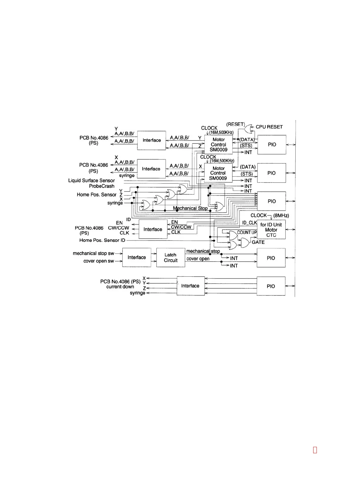
(19) Stepper Motor Control (U310, 311, 302, 305, 303)
With using two stepper motor control IC (SM0009: U310, 311), this circuit controls each stepper motor
of the X, Y, Z, volumetric syringe.
The motor home position sensor signal and the mechanical switch latch signal are taken as a OR
circuit, therefore, as soon as the mechanical switch is turned ON, the operation immediately stops.
Also, the Z-Axis sensor is taken as a OR circuit with the liquid surface detector sensor and the probe
crash sensor, therefore, in the case the probe is moving downward by these signals, the operation
immediately stops. The current down signal controlling the current of the driver when the motor stops
is output from P10 (U302, 305).
The ID Unit stepper motor is controlled by the CTC (U303) and the peripheral gates.
Figure 3-15:
Stepper Motor Control Circuit
(20) Vacuum Pump Control
This circuit controls the vacuum pump for aspirating waste.
(21) SV Control, Sampler Table Lock Control
This circuit controls two solenoid valves and the actuator for the sampler table locking.
(22) Buzzer
This circuit controls the buzzer ON/OFF by the output port.
(23) Mixing Motor Control
This circuit controls the stirrer motor ON/OFF by the output port.
The mixing motor driving power voltage is adjusted at VR101. The regulated voltage on the PCB No.
4086 is controlled by this VR101.
(24) Bus Interface
This circuit is composed by the Address Bus, the Data Bus, the Address Decoder (U203, 203, 205,
206, etc.), and the RD/WR signal generating circuit (U208).