CA-500 Series S/M 3-21 Revised December 2001
8
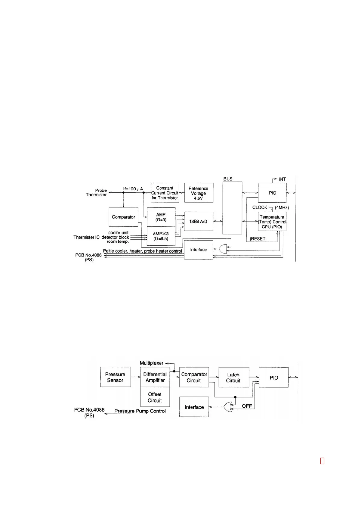
(17) Temperature Control Circuit (U401 ~ 412)
This circuit amplifies the four temperature sensor signals (for Reagent Cooler Unit, Detector Block,
Thermister, and Probe (Nozzle)), converts them to the digital signals by the 13 Bit A/D converter
(U412), analyzes them at the Temperature control CPU (U401), and outputs the control signals for
Detector Block heater, Probe heater, and Peltier cooler from each port.
Also, the temperature control CPU sends each sensor temperature data and the sensor controlled
value by the interface (U402, 403, 404) with the Main CPU (U201).
As the sensors for Cooler Unit, Detector Block and Thermister, the centigrade temperature sensor IC
(LM35DZ) is used and the sensor signal is amplified by 8.5 times at the amplifier unit.
In the case the sensor signal is cut off, each sensor signal line is pulled up or pulled down to avoid
over heating or over cooling.
As the temperature sensor for the Probe, a thermister is used. Approximately 100 µA constant
current is flowed in the thermister and the voltage is amplified by three times at the amplifier unit.
In the case the thermister is disconnected, or to avoid the thermal runaway when overheating due to
the abnormal control, the voltage is compared by the comparator (U408) and the Probe control signal
is forced to turn OFF when abnormal voltage occurred.
Each control signal for Detector Block heater, Probe heater and Peltier cooler, can be checked by the
LED status (D401, D402 and D403).
Figure 3-13:
Temperature Control Circuit
(18) Pressure Control Circuit (U518, 517, 516, 519, 520, 521)
This circuit controls the pressure to supply water to each unit from Rinse Bottle. This circuit is
composed by the pressure sensor, the differential amplifier, the Offset circuit and the Comparator
circuit, and the pressure pump is controlled by these signals.
The pressure is supplied from the pressure pump to the pressure sensor (U518) mounted on the
board, and the sensor signals are output in accordance with the supplied pressure. The Gain
controlled value and the Offset controlled value are added on this signal by the differential amplifier
and the signal is input in the comparator circuit(U516) to compare the voltage with the specified one.
In the case the pressure decreases in this circuit, the signal activating the pressure pump is output.
The other comparator circuit and the latch circuit (U519, 520, 521) are used for detecting the pressure
error.
Figure 3-14:
Pressure Control Circuit