CA-500 Series S/M 4-28 Revised December 2001
4.3.13 Position Adjustment Procedure of Catcher (“[29]immunoassy)
Adjustment Parameter: Catcher Position XYZ pulses of Detector Block
Summary: Adjust the catcher XY and Z positions of the detector block by setting the reaction
tube to the catcher.
Standard Position:
X direction: 5 pulses to the left of the line where the left surface of the reaction tube, when
descended, agrees the interior surface of the immunoassay well.
Y direction: The center of the catcher agrees the center of the reaction tube when the reaction
tube is descended.
Z direction: 2 pulses above the line where the bottom of the reaction tube agrees to the bottom of
the immunoassay well.
The upper edge of the reaction tube brim should be aligned with the lower surface of
the upper catcher part.
(1) XYZ Adjustment, X Correction
1) Place the reaction tube to the catcher.
2) Verify that the “[29]immunoassy” is shown on the left center of the screen. . If not, change to
“[29]immunoassy” by using [Pos. -] and [Pos. +] keys.
3) Move the catcher to the setting position by using [XY TEST] key.
4) Use [n], [p], [m], and [o] keys to adjust the reaction tube placed to the catcher to become the center
of the immunoassy well.
5) Press [Z TEST] key to descent the catcher.
6) Press [Tube Free] and [Tube Catch] keys to release and catch the reaction tube.
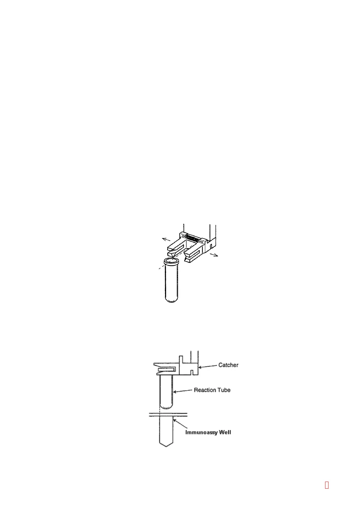
(a) Y direction: Use [n] and [p] keys to adjust the center of the reaction tube agrees the center of
the catcher.
Figure 4-3-26: Y Direction Adjustment
(b) X direction: Use [m], and [Æ] keys to adjust the horizontal position of catcher. The catcher
once ascends and then descends by pressing [Z ADJUST] key. Adjust the
reaction tube position in X direction to touch the left part of the inner wall of the
immunoassay well by repeating this operation.
Figure 4-3-27: X Direction Adjustment
8