4 DISPLAY AND CONTROL ELEMENTS
4.4 MHL380 D
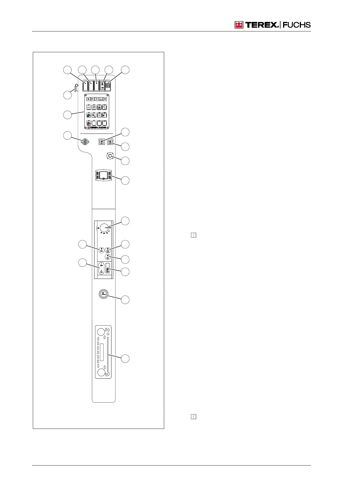
4.1.1 Operator control panel
MHL-NBXX-551
60
70 71 72 73 74
84
85
86
87
88
89
91
90
92
93
94
96
69
99
23 Control panel
0 Ignition lock
9 24 V socket
0 71 72 Not assigned
3 Clogged particulate filter indicator (op-
tional)
4 Warning buzzer – sounds in the event of
excess exhaust gas pressure as the re-
sult of a clogged particulate filter (option-
al)
4 Key switch (black) – deactivate overload
warning device (optional)/overload cut-off
(special equipment)
5 Key switch (blue) – reduce hydraulic oil
pressure or enable work movements with
the diesel engine stopped (function is only
active as an option)
6 Pushbutton for EMERGENCY STOP (op-
tional)
7 Supplementary heating lever (optional)
h
Device manufacturer's operating in-
structions
8 4-stage-switch blower
(heating and air conditioning system)
9 Button toggle for air flap
Telltale on: circulating air
Telltale off: external air (fresh air)
0 Button toggle for external temperature
display
1 Button toggle for air conditioning system
Telltale on: air conditioning system
switched on
Telltale off: air conditioning system
switched off
2 Button toggle for temperature setting
3 Digital display of external temperature
and operating status
4 Cigarette lighter
6 Radio, CD player (optional)
h
Manufacturer's operating instructions
9 Control panel

 Loading...