2.3 Seal the pipes with applicable seals to prevent contamination.
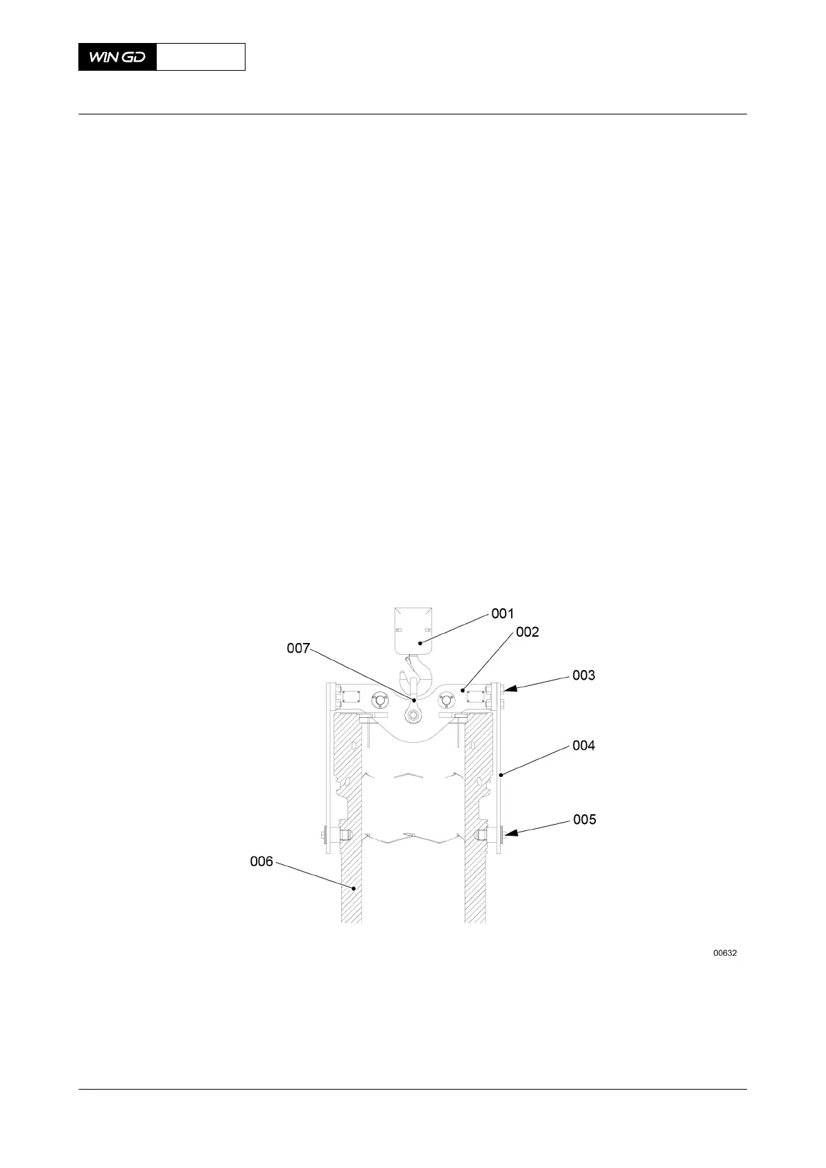
3 Attach the two plates (004, Figure 7-3) to the lifting tool (002) as follows:
3.1 Remove the two lifting tools from the lifting tool (002).
3.2 Attach the engine room crane (001) to the shackle (007).
3.3 Operate the engine room crane (001) to lift the lifting tool (002) to a sufficient
height.
3.4 Apply Molyslip Copaslip to the threads and surfaces that touch on the special
screw (005) and the eight M27 bolts and nuts (003).
3.5 Attach the two plates (004) in position on the lifting tool (002) with the eight M27
nuts and bolts (003).
3.6 Torque the four nuts and bolts (003), refer to section 16.1 Tightening
instructions.
4 Operate the engine room crane (001) to move the lifting tool (002) and plates (004) into
position on the cylinder liner (006).
NOTE: The connection between the plate (004) and the cylinder liner (006) relates to
the engine.
5 Torque the special screws (005) to the related value, refer to section 16.1 Tightening
instructions.
Fig 7-3 Lifting tool (example)
6 Operate the engine room crane (001, Figure 7-4) to lift the cylinder liner (003).
7 Move the cylinder liner (003) over the elastic bolts (002).
8 Lower the cylinder liner on to an applicable wooden underlay (004).
9 If necessary, put the cylinder liner (003) into safe storage, refer to section 7.1.3 Cylinder
liner - preserve.
X62DF
AA00-2124-00AAA-520A-A
Maintenance Manual Cylinder liner - remove
Winterthur Gas & Diesel Ltd.
- 175 - Issue 002 2020-10