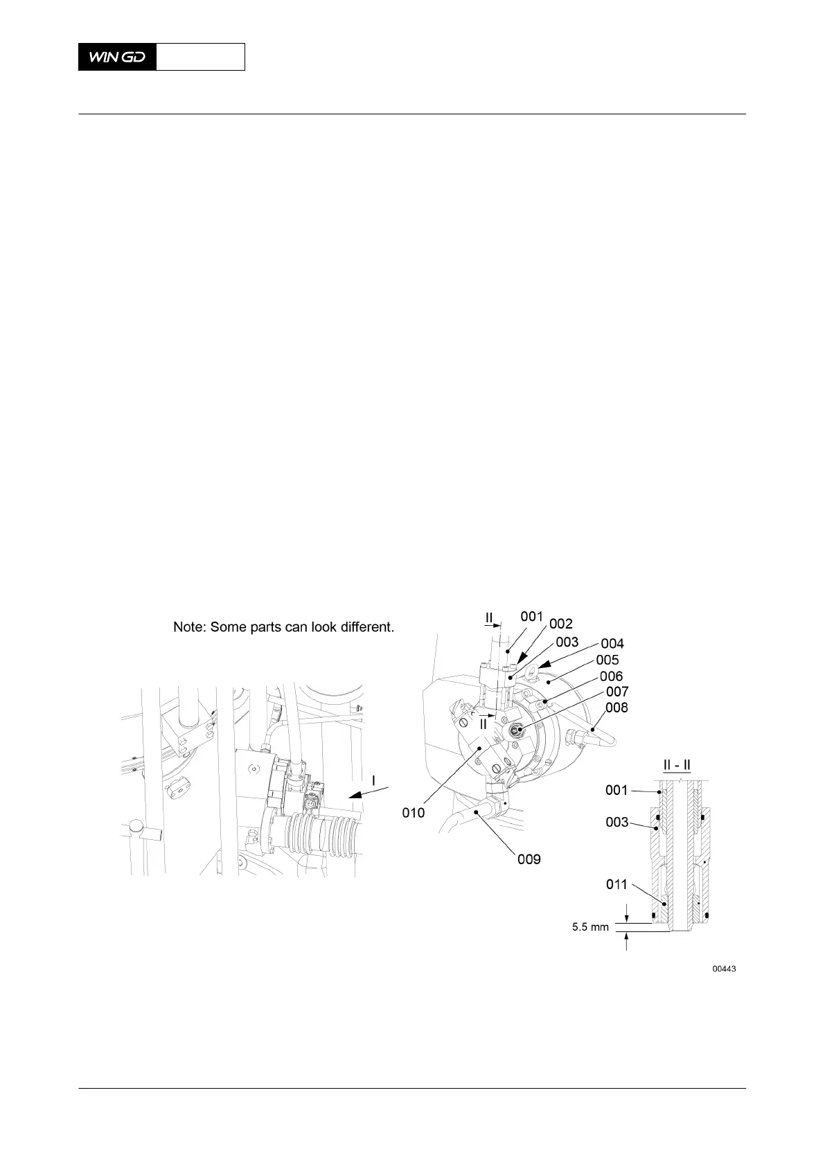
PROCEDURE
1 Attach the eye bolt (004, Figure 7-24) to the housing of the (GAV) (005).
2 Lift and move the GAV (005) to the applicable position.
3 Make sure that all surfaces that will touch are clean.
4 Apply Never Seez to the Allen screws (006).
5 Torque the Allen screws (006) to the correct value, refer to section 16.1 Tightening
instructions.
6 Attach the drain pipe (009) and the adjustable angle union to the GAV (005).
7 Attach the lubricating oil pipe (008) to the GAV (005).
8 Make sure that the sealing face of the oil pipe (001) has no damage. If there is damage,
grind the sealing faces.
9 Adjust the claw (011) with an open-ended wrench until there is a distance of 5.5 mm
between the claw and the end of the pipe (001).
10 Apply oil to the threads and surfaces that touch of the Allen screws (002).
11 Attach the flange (003) and the pipe (001) to the GAV (005) with the Allen screws (002).
12 Torque the Allen screws (002) to the correct value, refer to section 16.1 Tightening
instructions.
13 Connect the electrical connection to the rail valve (010).
Fig 7-24 Gas admission valve - install
14 Use the connection tool (001 Figure 7-25) to attach the electrical connection (1) to the
valve stroke sensor (2).
X62DF
AA00-2140-00AAA-720A-A
Maintenance Manual Gas admission valve - install
Winterthur Gas & Diesel Ltd.
- 221 - Issue 002 2020-10